ABSTRACT
LoRa is a long-range, low-power, low-bitrate, wireless telecommunications system, promoted as an infrastructure solution for the Internet of Things: end-devices use LoRa across a single wireless hop to communicate to gateway(s), connected to the Internet and which act as transparent bridges and relay messages between these end-devices and a central network server. This paper provides an overview of LoRa and an in-depth analysis of its functional components. The physical and data link layer performance is evaluated by field tests and simulations. Based on the analysis and evaluations, some possible solutions for performance enhancements are proposed.
LORA OVERVIEW
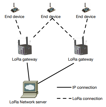
Figure 1. LoRa network architecture
A typical LoRa network is “a star-of-stars topology”, which includes three different types of devices, as shown in Figure 1. The basic architecture of a LoRaWAN network is as follows: end-devices communicate with gateways using LoRa with LoRaWAN. Gateways forward raw LoRaWAN frames from devices to a network server over a backhaul interface with a higher throughput, typically Ethernet or 3G.
Consequently, gateways are only bidirectional relays, or protocol converters, with the network server being responsible for decoding the packets sent by the devices and generating the packets that should be sent back to the devices. There are three classes of LoRa end-devices, which differ only with regards to the downlink scheduling.
THE LORA PHYSICAL LAYER
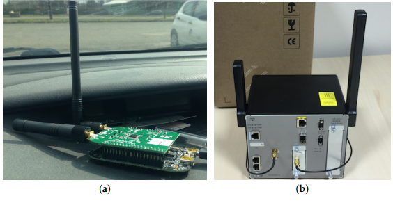
Figure 4. The LoRa testbed
(a) The LoRa end-device; (b) the LoRa gateway.
To verify whether the specified performance of LoRa receivers is reached in practice, a LoRa testbed is built. The Freescale KRDM-KL25Z development board with Semtech SX1276 MBED shield (Figure 4a) is used as the end-device, and a Cisco 910 industrial router is used as the gateway (Figure 4b). The gateway is connected to the network server provided by Thingpark (https://actility.thingpark.com) through Ethernet, so that the packet received can be monitored on the server side.
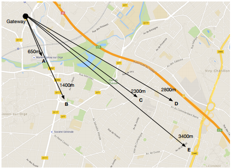
Figure 6. Map of LoRa field test
This experiment aims at testing the network coverage of LoRa. Tests were conducted in a suburb of Paris, with mainly low-rise residential dwellings. The temperature was 150C, and the ambient humidity was 55%. The gateway was located on the second floor of a house, outside the window. Five different test points were chosen, with the distance to the gateway as shown in Figure 6. The end-device was in a car during the tests.
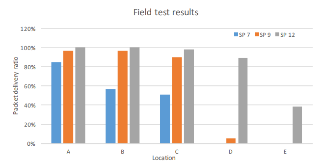
Figure 7. Packet delivery ratio of the LoRa field test
Figure 7 shows the packet delivery ratio of different spreading factors with various distances. About 100 packets are transmitted to the network server in each test with a sequence number. The higher spreading factors have better coverage, as discussed in Section: for a spreading factor of 12, more than 80% of packets were received at Point D (2800m), while no packet was received when using a spreading factor of seven.
THE LORAWAN PROTOCOL
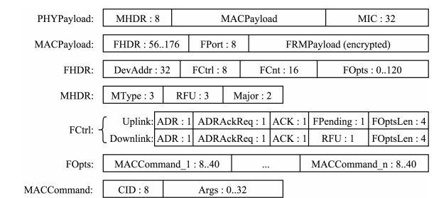
Figure 8. LoRaWAN frame format. The sizes of the fields are in bits
The message format is detailed in Figure 8. DevAddr is the short address of the device. FPort is a multiplexing port field. The value zero means that the payload contains only MAC commands. When this is the case, the FOptsLen field must be zero. FCnt is a frame counter. MIC is a cryptographic message integrity code, computed over the fields MHDR, FHDR, FPort and the encrypted FRMPayload.
MType is the message type, indicating among other things whether it is an uplink or a downlink message and whether or not it is a confirmed message. Acknowledgments are requested for confirmed messages. Major is the LoRaWAN version; currently, only a value of zero is valid. ADR and ADRAckReq control the data rate adaptation mechanism by the network server.
LORAWAN ANALYSIS
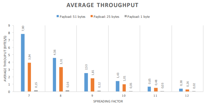
Figure 9. Maximum throughput attained by a single device using LoRaWAN
The experiment was conducted by having a device send data as soon as the channel limitations and the protocol allow it. Tests were conducted with six channels of 125kHz and using spreading factors from 7–12. No MAC commands were sent, so the size of the MAC header was always 13 bytes. The results, depending on the payload size, are visible in Figure 9, which are measured over about 100 packets transmitted in each test. Fifty-one bytes are the maximum payload size allowed by the implementation used for the tests.
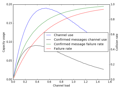
Figure 11. Link capacity usage and packet collision rate for a LoRaWAN network when using confirmed messages
For this simulation, we consider that the gateway does not send MAC commands to the device, so the acknowledgment message is always using a 13-byte MAC header and no payload. We also take these messages into account in the computation of the load, i.e., when the sum of the durations of all of the messages and their acknowledgments is equal to the duration of the simulation, the value of the load is one. The result is shown in Figure11.
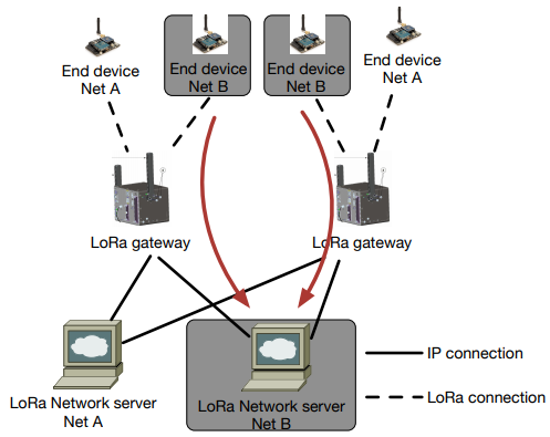
Figure 12. An example of shared gateways in LoRa. The gateways can forward the packet to different network servers
In the current specification, each gateway is dedicated to a specific network server, as shown in Figure 1. This means both the gateways and the data collected are “owned” by the entity that runs the only network server. In the future, it would be interesting to extend the function of the gateways so that they can forward the packet to specific network servers, as shown in Figure 12. This may effectively reduce the expense of devices and network deployment.
CONCLUSIONS
LoRa is a long-range and low-power telecommunication systems for the “Internet of Things”. The physical layer uses the LoRa modulation, a proprietary technology with a MAC protocol. LoRaWAN is an open standard with the specification available free of charge. This paper gives a comprehensive analysis of the LoRa modulation, including the data rate, frame format, spreading factor, receiver sensitivity, etc. A testbed has been built, to experimentally study the network performance, documented in this paper.
The results show that LoRa modulation, thanks to the chirp spread spectrum modulation and high receiver sensitivity, offers good resistance to interference. Field tests show that LoRa can offer satisfactory network coverage up to 3km in a suburban area with dense residential dwellings. The spreading factor has significant impact on the network coverage, as does the data rate. LoRa is thus well suited to low-power, low-throughput and long-range networks. This paper has also shown that LoRaWAN is an LPWAN protocol very similar to ALOHA. Its performance thus degrades quickly when the load on the link increases.
Source: Cisco Polytechnique chaire
Authors: Aloÿs Augustin | Jiazi Yi | Thomas Clausen | William Mark Townsley