ABSTRACT
This project developed to use smartphone as a robot controller since it’s more powerful and equipped with several sensors that are useful for robots. The project uses Android application as well as Arduino microcontroller to locate and control the robot via DTMF tone from distance.
Magnetometer and accelerometer sensor is used as input to trigger mobile robot movement for localisation purpose. The input sensor is designed to generate DTMF tone based on North Pole direction and force the robot to move only one direction referenced by North Pole. Several analyses have been done such as network provider analysis, robot operator analysis, sensor analysis as well as robot localisation analysis. The mobile robot was able to be controlled via developed Android application and all analyses regarding to robot performance is taken for future development purpose.
LITERATURE REVIEW
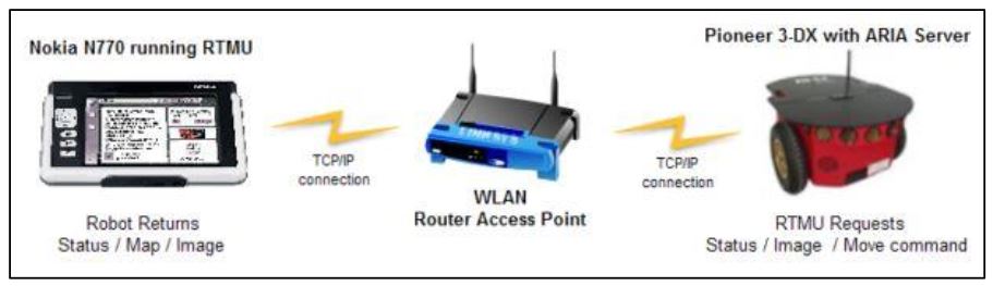
Figure 2.2: The P3DX robot overall system
Then a mobile robot called P3DX (Ehab, 2010) with WLAN connection as the interface medium and the Nokia N770 model is chosen as its “brain”. The GUI application named Robot Tele-operation Maemo User Interface (RTMU) essentially an ARIA (Advanced Robot Interface for Applications) client is an open-source software development kit based on C++ programming language. This GUI application will be programmed into the N770 and the robot movement is controlled via WLAN connection.
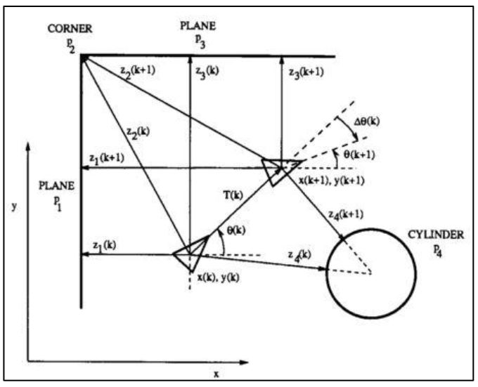
Figure 2.5: Localization by concurrent observation of several geometric beacons
This system is using the extended Kalman filter (EKF) to solve mobile robot navigation problem in a known environment. From a man-made indoor environment, each feature from the environment is modelled to be a geometric target. This geometric beacon is a special type of target that can be reliably observed in successive sensor measurements (ultrasonic sensor) and that can be accurately described in terms of a concise geometric parameterization. Based on Figure 2.5, the localization algorithm will be developed from this plant model.
![Figure 2.7: Landmark colors made out of A4 cardboard coloured paper; have 40 mm in radius and 210 mm in height [4]](http://cse.final-year-projects.in/wp-content/uploads/2017/12/p-02454-smartphone-based-robot-3.jpg)
Figure 2.7: Landmark colors made out of A4 cardboard coloured paper; have 40 mm in radius and 210 mm in height
![Figure 2.9: System layout diagram for the experiment [5]](http://cse.final-year-projects.in/wp-content/uploads/2017/12/p-02454-smartphone-based-robot-4.jpg)
Figure 2.9: System layout diagram for the experiment
METHODOLOGY
The components and hardware can be summarized according to a block diagram that is shown in Figure 3.2 while Figure 3.3 shows circuit diagram for a single motor developed by Fritzing software. Major components are two DC geared motors (SPG30E-30K) with encoder, the 10A NMOS H-Bridge motor driver, the Arduino Uno microcontroller, the DTMF module (MT8870), and a smartphone.
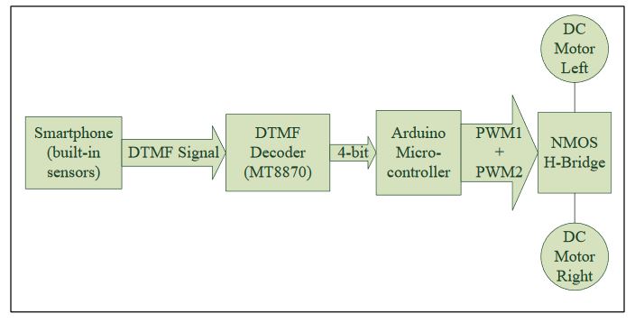
Figure 3.2: The block diagram of hardware development
The model is formed by quadrature Hall Effect encoder board which is designed to fit on the rear shaft of the DC motor as shown in above figure. Two Hall Effect sensors are placed 90° apart to sense and produce two outputs signal named A and B which is; 90° out of phase and allowing the direction of rotation to be determined. For further understanding, Table 3.1 (a) and (b) is showing the state diagram while in Figure 3.6, it is showing the waveform signal that will be produced by the encoder; consequence from the rotational movement of the DC motor.
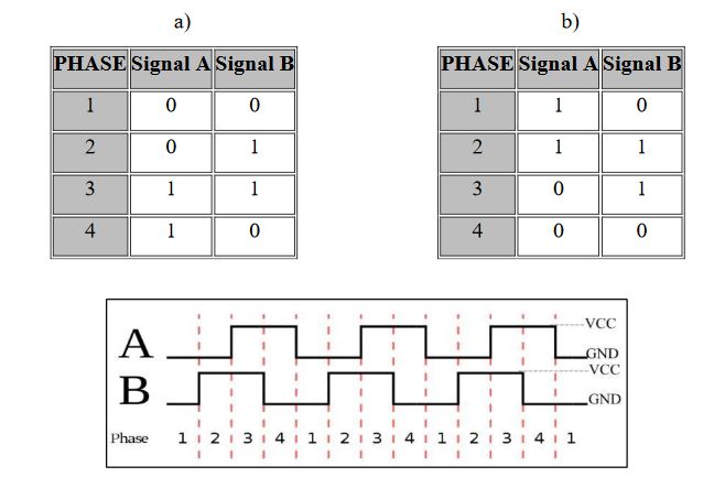
Figure 3.6: The waveform signals
A gyroscope is a device that senses an angular velocity. This applied by the Coriolis Effect theorem. Based on Figure 3.12, the Coriolis Effect happens when there is a mass that’s moving and the frame of reference is rotating. So when that happens, it will produce a fictitious force on the mass and it can be known how the frame of reference is rotating. For the analogy, the Earth is rotating, so the Earth’s rotation has some impact on things for example, weather systems effect.
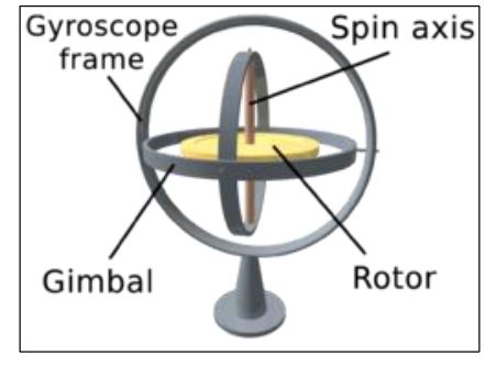
Figure 3.12: A visual of gyroscope
Source: University Tun Hussein On Malaysia
Author: Nik Firdaus Bin Nik Mahmod