ABSTRACT
Small scale fading signals resulting from multipath propagation can cause signal strength variations in the range of several dB. Resulting from the fluctuating signal strengths, the wake-up packet reception rate can decrease significantly. Using antenna diversity can greatly mitigate these effects. This article presents a novel wireless sensor node with wake-up receiver that uses an equal-gain diversity method with two antennas in the wake-up path.
Summation of the two diversity branch signals is done after the passive demodulation of the incoming signals. As a result, the wireless sensor node requires almost no additional active parts that would increase power consumption. Furthermore, we demonstrate experimentally the improved wake-up robustness and reliability achieved by this diversity technique in a multipath environment.
BACKGROUND
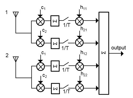
Figure 1. Schematic of a receiver with maximal ratio combining diversity for two input channels
Phase alignment can be achieved, for example, by a cophase and sum circuit that can be realized, for instance, as a rake receiver that has the ability to demodulate each incoming signal independently. By correlating the incoming signals to delayed replica versions, a rake receiver can detect and reduce the relative phase offsets originating from the multipath propagation. Figure 1 illustrates a generic rake receiver with two input channels.
HARDWARE
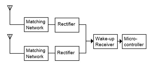
Figure 3. Block diagram of a low-power wake-up receiver with antenna diversity. Each diversity branch consists of antenna, matching network and rectifier
Figure 3 illustrates the block diagram of the proposed diversity system. As can be seen, the two antenna paths both include a matching network and a rectifier to demodulate the incoming wake-up messages. The two branches are combined after the demodulation stage and then fed into the wake-up receiver.
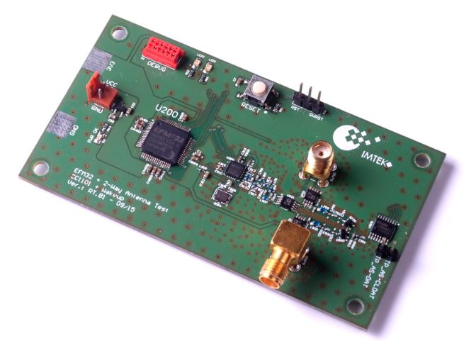
Figure 6. Photo of the wireless sensor node with equal gain diversity
Figure 6 shows a photo of the wireless sensor node with antenna diversity. To feature multiple antennas, the board is equipped with two antenna ports, which are connected to an ADG918 antenna switch from Analog Devices. By inserting a third antenna switch, it is possible to use both antennas as input and output. Due to the three extra antenna switches, the node has an additional power consumption of less than 3 μA compared to the power consumption of the node introduced above.
EXPERIMENTAL RESULTS
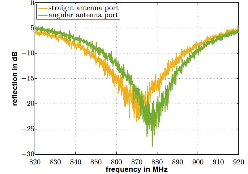
Figure 8. Reflections measured at the straight (yellow) and angular (green) antenna input ports over frequency
To verify the impedances of both antennas, a frequency sweep from 820 Mhz to 920 Mhz was performed and the reflections were measured with a network analyzer. The measurement results are plotted in Figure 8 that illustrates the reflection of the straight antenna in yellow and the reflection of the angular antenna in green. As can be seen, the minimum reflection is at approximately 870 MHz for the straight antenna and at approximately 878 MHz in the case of the angular antenna.
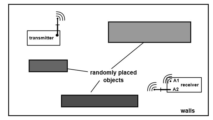
Figure 12. Multipath laboratory setup with randomly placed objects
The blue circles show the results for the straight antenna system, the green squares for the angular antenna system and the yellow markers depict the equal-gain diversity results. In this particular experiment, the equal-gain system outperformed both of the other configurations in all measurements, as can be seen in Figure 12.
CONCLUSIONS
The ultra low-power wireless sensor node presented in this article successfully demonstrated the use of equal-gain-combining in combination with a low-frequency wake-up receiver. Resulting from the wake-up frequencies in the kilohertz range, energy-demanding phase control circuits are not required. The implemented and investigated equal-gain wake-up diversity node requires only two additional antenna switches to combine the multiple input signals and that increase the power consumption only marginally.
The polarization diversity technique was implemented, although this is no limitation and other diversity techniques like space diversity could also be utilized. It could be verified that the antenna diversity achieved 3 dB gain under ideal laboratory conditions where the signals were free from noise, but not phase aligned. A laboratory multipath environment experiment confirmed the performance gain between 0.2 and 2.5 dB of the equal-gain wake-up diversity system.
Source: University of Freiburg
Authors: Timo Kumberg | Robert Tannhaeuser | Leonhard M. Reindl