ABSTRACT
A double-negative metamaterial-inspired antenna is presented for mobile wireless applications. The antenna consists of a semi-circular radia ting patch and a 3 × 4 hexagonal shaped metamaterial unit cell array in the ground plane. The antenna is fed with a 50 Ω microstrip feed line. The electric di mensions of the proposed antenna are 0.20 λ × 0.26 λ × 0.004 λ, at the low-end frequency.
The proposed antenna achieves a −10 dB impedance with a bandwidth of 2.29 GHz at the lower band and 1.28 GHz at the upper band and can operate for most of the m obile applications such as upper GSM bands, WiMAX, Bluetooth, and wireless local area network (WLAN) frequency bands. The focused novelties of the proposed antenna are its small size, multi-standard operating bands, and electromagnetic absorption reduction at all the operating frequencies using the double-negative metamaterial ground plane.
DESIGN OF THE PROPOSED ANTENNA AND UNIT CELL
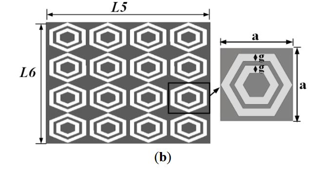
Figure 1. (a) Schematic diagram of the antenna; (b) Unit cell array and unit cell configuration
The proposed metamaterial antenna and unit cell structure is presented in Figure 1. A hexagonal shaped metamaterial unit cell array is designed and fabricated on a 0.8 mm thick FR-4 substrate. The proposed antenna is also printed on a 0.8 mm thick FR-4 substrate of dimensions 45 × 35 mm2. The antenna is incorporated with a semi-circular patch and a hexagonal shaped metamaterial array in the ground plane.
DNG METAMATERIAL CHARACTERIZATION
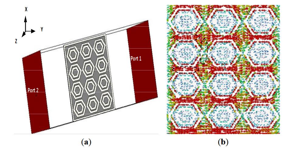
Figure 2. (a) Simulation arrangement of a unit cell array of metamaterial characteristics; (b) Surface current distribution at 1.97 GHz
The metamaterial structure interacts with electromagnetic waves and shows some special properties. For characterizing the metamaterial, the array structure was positioned between two waveguide ports on the negative and positive x-axis and excited by a transverse electromagnetic (TEM) wave. The perfect electric conductor (PEC) boundary and the perfect magnetic conductor (PMC) boundary were defined along the y and z axes, respectively, as shown in Figure 2a.
ANTENNA PERFORMANCE ANALYSIS
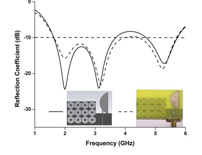
Figure 5. Simulated and measured reflection coefficients of the proposed antenna
The reflection co efficient of the proposed antenna has been measured using a PNA network analyzer, presented in Figure 5. The proposed antenna achieved measured impedance bandwidths of 2.29 GHz (1.66–3.95 GHz) and 1.28 GHz ( 4.45–5.73 GHz), enabling it to operate in the frequency bands of GSM (1800, 1900, 2100), WiMAX (3.2–3.6 GHZ), Blue tooth (2.4 GHz), and WLAN (5.47–5.9 GHz).
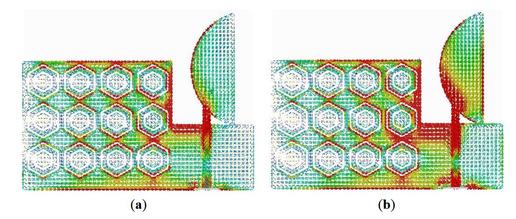
Figure 6. Surface current distribution of the proposed antenna at (a) 1.8 GHz; (b) 2.4 GHz
To observe the physical phenomenon of the proposed antenna, the current distribution at different frequencies is analyzed. The surface current distribution is obtained from simulation software for different frequencies, as shown in Figure 6. A stronger surface current distribution is observed along the metamaterial ground plane and near the feed line.
ELECTROMAGNETIC ABSORPTION ANALYSIS
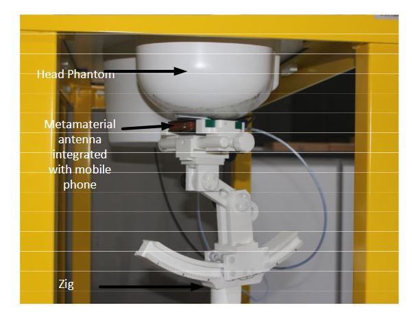
Figure 9. SAR measurement in the Satimo SAR measurement lab
The SAR values of the proposed antenna have been measured using the Satimo COMOSAR measurement system. The system consists of a robot to move the field probe, head phantom, and test zig, as shown in Figure 9. The field probe is connect ed to the system computer. The head phantom is filled with liquid, which maintains the equivalent dielectric properties of the human head.
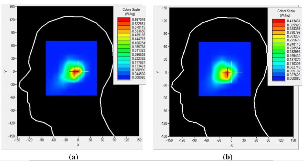
Figure 10. 1 g SAR measurements of the proposed antenna at (a) 1.8 GHz and (b) 2.4 GHz
The measurement was performed at 1.8 and 2.4 GHz. The measured 1 g SAR value of the proposed antenna is shown in Figure 10, and the simulated and measured results are listed in Table 2. It is seen from Table 2 that the proposed antenna has succeeded in a large-scale reduction of SAR values as compared to reported antennas.
CONCLUSIONS
A low-profile metamaterial antenna has been presented for low electromagnetic absorption mobile applications. The proposed antenna with a metamaterial structure was found to reduce the peak SAR values without degrading the antenna performance. The measured 1 g SAR values of the proposed antenna were 0.667 W/kg and 0.413 W/kg at 1.8 GHz and 2.4 GHz, respectively, which are 58.31% and 74.19% lower than the standard safety guidelines. Therefore, the human body can be sheltered from the hazardous effects of the electromagnetic radiation using the proposed antenna.
Source: University Kebangsaan Malaysia
Authors: Touhidul Alam | Mohammad Rashed Iqbal Faruque | Mohammad Tariqul Islam
>> Antenna Design Based Projects List for Engineering Students
>> More Wireless Bluetooth Projects for Engineering Students