ABSTRACT
Non-linear high-power devices produce electromagnetic noise (EMN) sources of great intensity that can disrupt and damage the surrounding electrical equipment and devices. This radiative phenomenon is very common at facilities where pulsed power generators are required, particularly those that are needed to produce dense transient plasma experiments.
These conditions are found at the Chilean Nuclear Energy Commission (CCHEN), due to the presence of pulsed power generators that switch large currents (kA-MA) in short times (10–100 ns). In order to characterize and establish conditions to mitigate the effects of the EMN on nearby devices, a measurement system based on an ultra-high frequency (UHF) dipole antenna was developed. We evaluated the system measuring the EMN emanated from a plasma focus device, the PF-400J.
Measurements at the place indicated broadband and intense electric fields that can couple to nearby cables and equipment (10–300 MHz bandwidth, up to 350 V/MHz spectral intensity, 100 V coupled voltage). Based on these measurements a compact and simple protection system was designed, built and tested, capable of effectively mitigating the high levels of EMN. The proper EMN impact mitigation indicates the correct operation of the suggested system. The developed system can be of interest to the energy community by facilitating EMN measurement produced by arc discharges.
ELECTRICAL NOISE
In general, the electrical noise can be classified into three types—capacitive, inductive and electromagnetic interference—depending on its coupling mechanism. These types of disturbances, which in some cases may be of great amplitude, are directly coupled to the lines or power cables of any device or electrical equipment, causing irreparable damage to the insulation systems and electronic components of the latter.
CHARACTERIZATION AND CALIBRATION OF THE MEASUREMENT SYSTEM
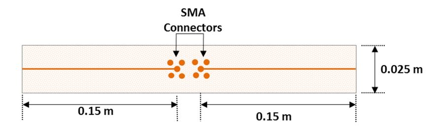
Figure 3. Small dipole antenna with coaxial balun used as electric field probe. The arms are connected through SMA ports to coaxial cables
After numerous laboratory tests, a 0.3 m small dipole antenna with a coaxial balun (Figure 3) was implemented as sensor. The final prototype antenna was printed on a circuit board of 0.30 m long and 0.025 m wide. The conductive wire was set to a width of 1.5 mm and both ends were connected to two coaxial connectors that are used as the output of the antenna. It was calibrated with a set of AF which allows the estimation of the electric filed intensity from the voltage signal at the antenna terminals for each frequency of interest.
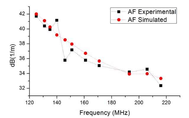
Figure 6. Experimental and simulated antenna factors versus frequency. Connecting lines are referential, to help the reader
The experimental validation of the AF was made for sinusoids with frequencies ranging from 100 MHz and 220 MHz, imposed by the operational range of our RF generator and the detection of strong enough signals in our oscilloscope. Then, the 0.3 m-dipole was used as receiver and the amplitude of the detected signals were recorded. The AF measured and simulated within the frequency range for the 0.3 m-dipole are shown in Figure 6.
MEASUREMENT OF AN EMN CASE
The noise signal and its FFT are shown in Figure 8. The data shows two electromagnetic noise peaks similar to the ones seen in the previous experiment where the 0.3 m-dipole antenna was used to probe the EM noise. The perturbation has an amplitude exceeding 100 V peak to peak and frequency components reaching 200 MHz.
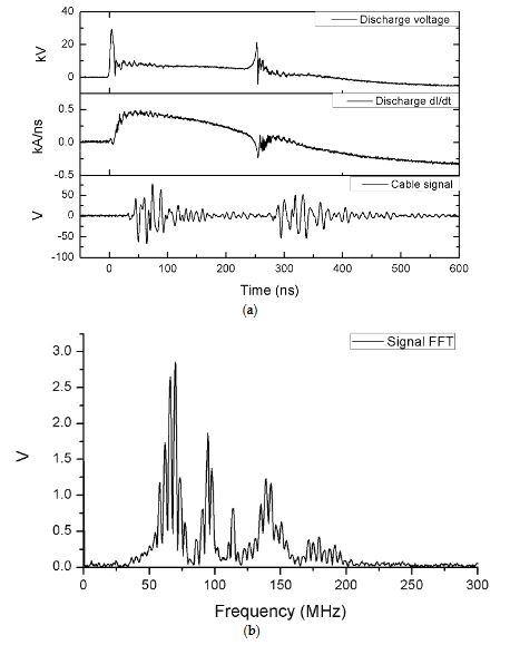
Figure 8. Time evolution of the signals in the discharge for the cable coupling measurements
PROTECTION SYSTEM
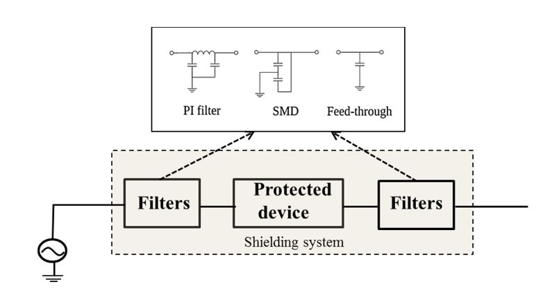
Figure 9. Protection system scheme and the different filters used
This enabled the protection of the device from the noise that is coupled in each of the cables, which act like antennas to certain frequencies. The second protection mechanism corresponds to a shielding system based on a Faraday cage that attenuated and successfully protected (from the direct radiation that arrived as consequence of the high amplitude electric fields) the electronics of the devices including the filtering step of the first protection mechanism. Figure 9 shows the protection system scheme and its details are described in the following section.
DISCUSSION
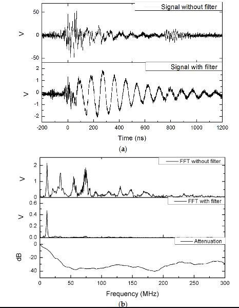
Figure 11. Signal obtained with the application of the protection system
The performance of the protection system was assessed by measuring the electric field and the voltage induced in the controller cable. The ultimate test was made with a turbo molecular pump controller operating inside a Faraday cage while the PF-400J discharge was running. After hundreds of cycles, the electronic device continued working normally without any evidence of failure. In Figure 11 the results obtained experimentally are shown when the protection system is used in the turbo molecular pump controller/control cable system.
CONCLUSIONS
A low cost compact electromagnetic noise measurement system based on a 30 cm dipole antenna was designed, developed and tested. The measurement procedure of electric field requires the calibration of the antenna with a coaxial balun. The procedure includes the calculation and validation of antenna factors, which are used to estimate the electric field from the voltage signal at the terminals of the antenna.
The validation of the antenna factors was performed by following the standard site method. The system was tested by measuring the electromagnetic noise intensity generated for the operation of a plasma device, the PF-400J. The measured electromagnetic noise radiated from the PF-400J had peaks close to 350 V/m at frequencies below 70 MHz and faster oscillations had an average of 10.8 V/m. The electromagnetic noise estimation made with the antenna probe was compared with measurements obtained with a 3 m cable.
The measurements in the cable had an amplitude over 100 Vpp and significant frequency components up to 200 MHz. The main features estimated with the antenna probe were seen within the 3 m-cable confirming the effectiveness of the measurement system. Based on the antenna probe measurements, a protection system with filters for the cables crossing its boundaries and a shielding system for the electronics of the equipment was designed.
The characteristics of the box and the filters were selected to attenuate the perturbations passing through them by at least one order of magnitude. The constructed system had an attenuation over 20 dB for electric fields and 28 dB for voltage signals in frequencies below 300 MHz. The equipment installed inside the cage displayed no signs of perturbations when exposed to electromagnetic noise, which confirms the effectiveness of the electric field measurements and the protection devices.
Source: University of Chile
Authors: Ismael Escalona | Gonzalo Avaria | Marcos Diaz | Jorge Ardila-Rey | Jose Moreno | Cristian Pavez | Leopoldo Soto
>> Project Report on Microstrip Patch Antenna Design for Final Year Students