ABSTRACT
General purpose receivers of today are designed with a broad bandwidth so that the receiver can accept a wide range of signal frequencies. These receivers usually accept one signal along with an y interference that is included. To increase the signal detection capabilities of the wide band receiver, a design for a receiver that can detect two signals is needed.
One of the requirements for this receiver is that the second weak signal needs to be processed in a timely manner so that the receiver can recognize it. To remedy the problem, a module was developed using wavelet-based techniques to remove spurs from the incoming signals to allow easier detection. The main basis for this concentration on wavelets comes from the way wavelets break down signals into portions (called resolutions) that allow easier determination of detail importance.
Utilizing the multi-resolution attributes of the discrete wavelet transform, a way to remove signal spurs is made possible. When removing the signal noise from the signal, the two signal dynamic range of the system is increased, as this module is applied to multiple receiver systems for comparison of performance. Implementation of this system was originally done in C as well as MATLAB, but later is being implemented in VHDL with simulations done for verification of functionality.
THEORY AND BACKGROUND
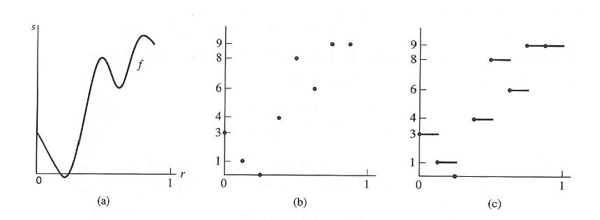
Figure 2.1: (a) Signal, (b) Sample (c) Approximation for Haar Wavelet
This wavelet transform relies on a rectangular function, which utilizes the basic approximating functions that would estimate the shape and detail of the waveform that is being transformed. Simplified, the Haar wavelet transform uses an approximating function that is a variation of a step function.
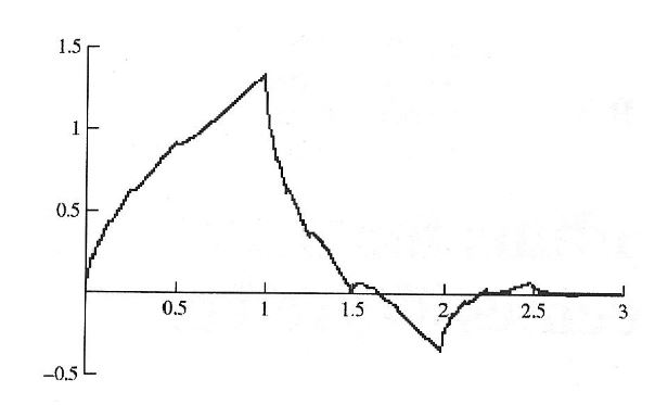
Figure 2.2: Daubechies Wavelet
The Daubechies wavelet is calculated in this fashion. It can be seen that the Daubechies wavelet method utilizes vanishing moments. Vanishing moments are described as a point in the function where it dips below the frequency axis. Vanishing moments contribute to the smoothness of the transformed wavelet because they allow the system to compensate for the differences in the transfer function without sacrificing expensive hardware implementation.
METHODOLOGY

Figure 3.1: Block Diagram of Steps
The block diagram above depicts the flow of the system a s it is being used for simulations. Each block is described in the next sections. The receiver is also designed and implemented in hardware. The detailed implementation of the hardware is described in Section 3.7.
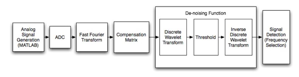
Figure 3.4: Signal Detection Through Thresholding
For the signals that are detected, they are still in the frequency domain. Signal detection is implemented in the software by using MATLAB code, which deals directly with the output of the C++ inverse transform function. An example of signal detection through thresholding is shown above.
RESULTS AND DISCUSSION
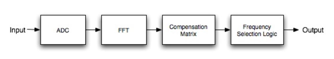
Figure 4.1: General Flow of Receiver Design without De-noising
As previously mentioned in Chapter 2, the compensation matrix relies on a set of calculated outcomes of the FFT, and therefore, subtracts the value that is pre-calculated from the actual signal data, exposing the second signal and reducing the actual noise in the signal.
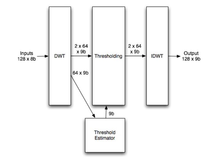
Figure 4.9: De-noising Function Block Diagram
The inputs to the discrete wavelet transform is 128 element set of 8 bit data from the compensation table. Each element of the data is assumed to be a positive number because of normalization from the compensation block. However, after a discrete wavelet transform, there are some coefficients that will be negative because of the filter coefficient values used.
CONCLUSION AND RECOMMENDATIONS
Conclusion
For effective signal processing that performs beyond a receiver on chip design with a compensation table, the discrete wavelet transform-based de-noising function is a valid solution. The discrete wavelet transform breaks down the incoming signal into high pass and low pass components. Low pass components are considered small details while high pass components are considered large details. Because spurious signals are considered small details in a discrete wavelet transform domain, thresholding is required to remove the spurious signals. When the thresholding is completed, the inverse transform reassembles the signal to the original signal domain.
Recommendations
I recommend an implementation of the discrete wavelet transform with greater number of bits for better precision and for the design to further improve performance of the receiver on chip design. Because the maximum number of bits for the coefficients to have perfect precision is 19 bits, I would recommend that a 19 bit design be pursued to have a complete design. The only drawback to this design would be that the increase in bits will require a larger space for the LUTs because the values required will be stored as 256 values, each being 19 bits. For negative numbers, there will be 512 values, each being 19 bits.
Source: Wright State University
Author: Tony Chiang
>> More Matlab Projects on Signals and Systems for Final Year Students