ABSTRACT
The use of global navigation satellite system (GNSS) antenna arrays for applications such as interference counter-measure, attitude determination and signal-to-noise ratio (SNR) enhancement is attracting significant attention. However, precise antenna array calibration remains a major challenge. This paper proposes a new method for calibrating a GNSS antenna array using live signals and an inertial measurement unit (IMU).
Moreover, a second method that employs the calibration results for the estimation of steering vectors is also proposed. These two methods are applied to the receiver in two modes, namely calibration and operation. In the calibration mode, a two-stage optimization for precise calibration is used; in the first stage, constant uncertainties are estimated while in the second stage, the dependency of each antenna element gain and phase patterns to the received signal direction of arrival (DOA) is considered for refined calibration.
In the operation mode, a low-complexity iterative and fast-converging method is applied to estimate the satellite signal steering vectors using the calibration results. This makes the technique suitable for real-time applications employing a precisely calibrated antenna array. The proposed calibration method is applied to GPS signals to verify its applicability and assess its performance. Furthermore, the data set is used to evaluate the proposed iterative method in the receiver operation mode for two different applications, namely attitude determination and SNR enhancement.
SYSTEM MODEL
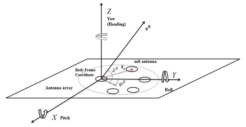
Figure 1. Antenna array configuration in the body frame coordinate system
Assume an N-element antenna array with an arbitrary configuration placed on a platform which is fixed with respect to the body frame coordinate system. In this configuration, one antenna is chosen as a reference antenna. For the sake of simplicity, it is assumed that the origin of the body frame coordinate system is located at the reference antenna location shown in Figure 1.
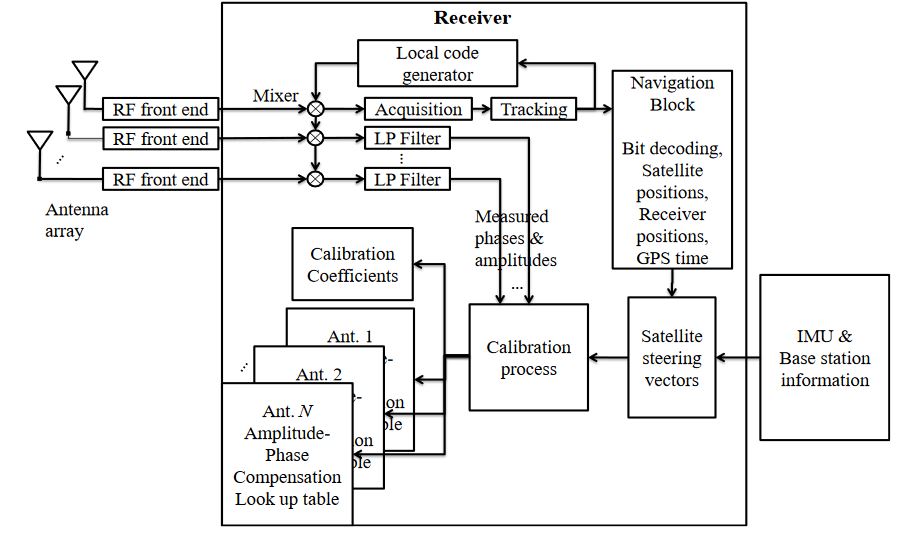
Figure 2. Multi-antenna receiver structure in the calibration mode
In the calibration process using a multi-antenna receiver, acquisition, tracking and positioning procedures can be only performed for the received satellite signals at the reference antenna (reference antenna) and the generated local codes can be used to despread the received signals at the other antennas (secondary antennas) as shown in Figure 2.
PROPOSED METHOD
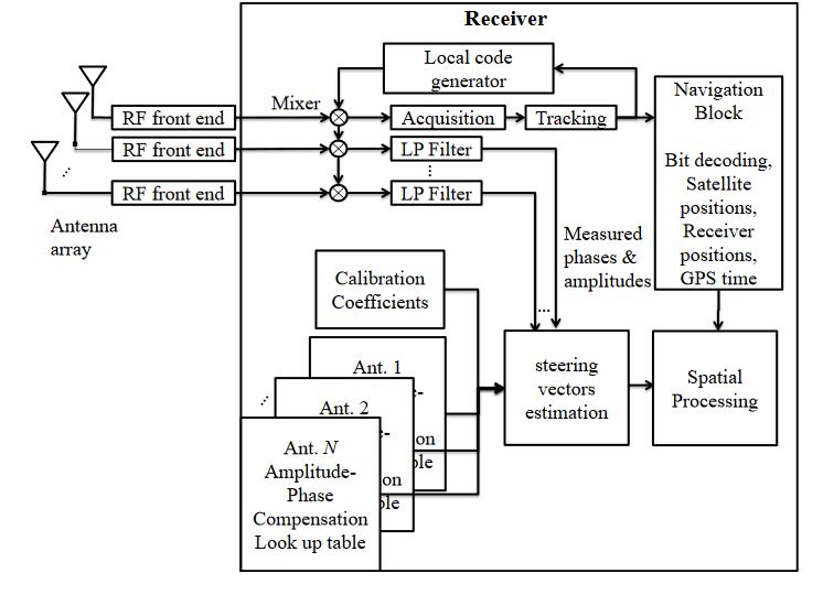
Figure 3. Multi-antenna receiver structure in the operation mode
The block diagram of a multi-antenna receiver in the operation mode is shown in Figure 3. It is worth mentioning that in order to estimate satellite signal steering vectors, position information is only used to calculate the azimuth and elevation angles of incident signals in the ENU coordinate system. These angles can be accurately estimated even with a low cost GNSS receiver (due to the long distance between satellite and the receiver).
TESTING
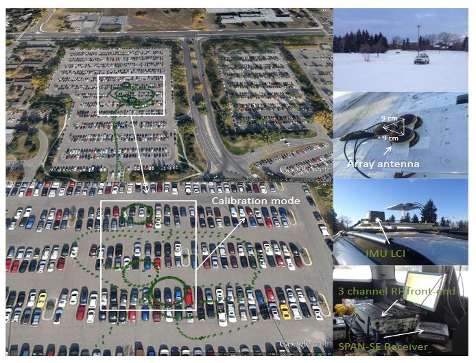
Figure 4. Data collection set up
The data collection setup and the test trajectory are shown in Figure 4. In order to operate under an open-sky environment, a parking lot was chosen for the data collection. This parking area is almost surrounded by empty fields (low multipath). Circular motion was performed for the calibration process to cover all azimuth angles. In order to cover all possible elevation angles, the circular motion should be repeated during several time intervals with long enough separations to allow satellites to move significantly in the sky.
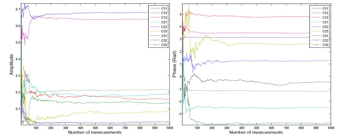
Figure 9. Amplitude and phase of the estimated calibration coefficients
Figure 9 shows the amplitudes and phases of the estimated calibration coefficients from the first stage of the calibration process. The plots illustrate the estimated elements of the matrix C versus the number of measurements from the first minimization in Equation (12). The results show that after a few hundred measurements, the estimated coefficients do not change significantly.
CONCLUSIONS
A novel two-stage precise calibration method using satellite signals for GNSS applications was proposed. In this method, all of the main uncertainties in the calibration process were modeled and it was shown that they could be separated into two parts; one is constant and the other one consists of DOA-dependent parameters. One solution for the associated optimization to this problem was introduced in the form of two eigenvalue decomposition problems.
Although the estimated constant term could provide coarse estimates of satellite steering vectors, for more precise calibration the second stage provided compensation amplitude and phase for each incident signal corresponding to its DOA in a form of a set of look up tables for each antenna element. The proposed two-stage calibration process not only simplified the interpretation of uncertainties, but also was used to come up with an iterative method with a fast convergence to accurately estimate satellite signal steering vectors.
The effectiveness of this method in both calibration and receiver operation modes was evaluated by using a set of collected GPS signals in two different GNSS multi-antenna applications. Although an IMU unit was employed in this case for calibration and its performance evaluation, heading, roll and pitch angles could also have been provided by the carrier phase measurements obtained by the antenna array using standard GNSS attitude determination methods.
Source: University of Calgary
Authors: Saeed Daneshmand | Negin Sokhandan | Mohammad Zaeri-Amirani | Gerard Lachapelle