ABSTRACT
In this paper, real-time monitoring of multiple lead-acid batteries based on Internet of things is proposed and evaluated. Our proposed system monitors and stores parameters that provide an indication of the lead acid battery’s acid level, state of charge, voltage, current, and the remaining charge capacity in a real-time scenario. To monitor these lead–acid battery parameters, we have developed a data acquisition system by building an embedded system, i.e., dedicated hardware and software. The wireless local area network is used as the backbone network.
The information collected from all the connected battery clients in the system is analyzed in an asynchronous transmission control protocol/user datagram protocol-based C server program running on a personal computer (server) to determine important parameters like the state of charge of the individual battery, and if required, appropriate action can be taken in advance to prevent excessive impairment to the battery. Further, data are also displayed on an Android mobile device and are stored in an SQL server database. We have developed a real prototype to devise an end product for our proposed system.
SYSTEM MODEL
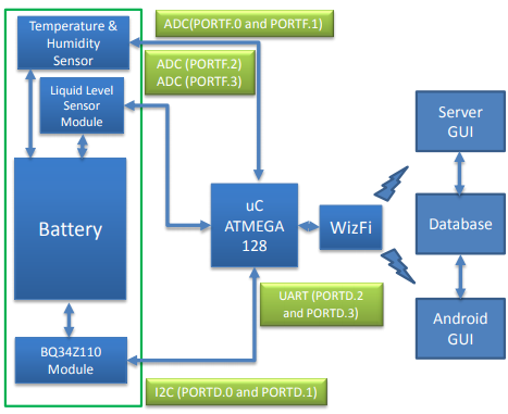
Figure 1. Block diagram of the proposed system. ADC: analog to digital converter; GUI: graphical user interface
The block diagram of our proposed system is presented in Figure 1; it includes a temperature and humidity sensor module, a liquid level sensor module and a BQ34Z110 module. The temperature and humidity data is estimated around the battery with the use of a chipcap-D sensor. The battery’s acid level, one of the most important parameters to be determined, is evaluated through an electrolyte level sensor module explained in detail in the next subsection. The battery’s important parameters, namely, the full charge capacity, the remaining charge capacity, the state of charge, voltage, and average current are assessed through the BQ34Z110 module.
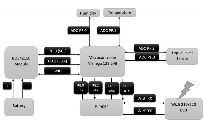
Figure 2. Pin map detailed diagram of the proposed system with the corresponding input
For a clear representation and working procedure, the pin map detailed diagram of our proposed system, with the corresponding inputs and ports, is shown in Figure 2. It should be observed that in our proposed system the communication between the various parts of the system is done using WLAN technology, considering the mobility of the vehicles and the batteries in an industrial environment. The vehicles are self-governing and can connect to any of the gateways installed in the premises of the industry.
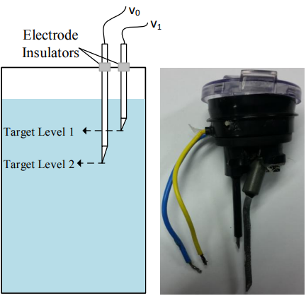
Figure 3. Electrolyte level sensor
Based on this, we have developed a simple and yet cost-effective two-electrode-based electrolyte/liquid level sensor for our proposed method. The sensor can measure two different levels with a very high accuracy. The sensor is shown in Figure 3. Two electrodes are dipped inside the battery according to predefined targets. A thin film of electrolyte is always present on the inside walls of the cells, therefore, the electrodes are positioned so that they do not touch the walls.
When the electrode touches the electrolyte, a current flows through the corresponding electrode connected across the negative terminal of the battery. The potential difference across the output of the electrodes and the battery negative terminal is stepped down using a LM7805 regulator, as high power can damage the microcontroller. The output is then fed to the microcontroller at ports PF2 and PF3. The microcontroller then senses the liquid level in the cell of the battery and sends the data to the server through the WizFi.
TESTBED IMPLEMENTATION, PROTOTYPE, AND SOFTWARE DEVELOPMENT
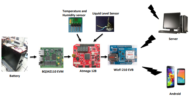
Figure 7. Basic setup of the proposed system
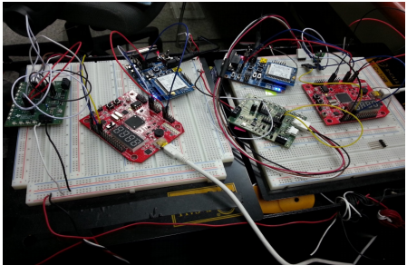
Figure 8. Proposed system battery testbed
The testbed implementation,prototype, and software development for our proposed method is presented in this section. The basic setup and testbed is shown in Figures 7 and 8, respectively. The BQ34Z110EVM board is connected to a microcontroller AtMega128a. We have used Port F to connect the analog input to the A/D converter.
Port F is an input port only. The inputs of the humidity, temperature, and the liquid sensors are fed to port F as humidity PF.0, temperature PF.1 and both the outputs of the liquid level sensor to PF.2 and PF.3. Thus, the temperature and humidity sensor are connected to port PF.1 and PF.0 while the both the outputs of the liquid level sensor are connected to PF.2 and PF.3 of the microcontroller.
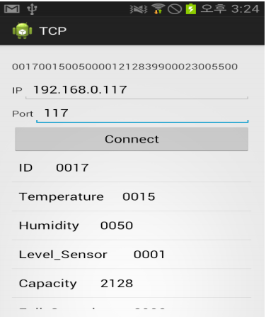
Figure 17. Android application program
Considering the mobility of the vehicle in an industrial environment, it will be difficult for the vehicle’s operator to access the server and obtain the details of the battery. Therefore, we have designed a simple yet effective TCP socket-based android application that can be easily installed on the operator’s android device and can be executed at any time by the operator on the run.
Our android application in a running condition is shown in Figure 17. The operator should know the battery (device) IP address and port number so that it can be used to receive the serial data frame of a particular battery on a click of the connect button. The data of the data frame from single client is divided into its respective 4 bits and displayed in the columns separately, as shown in Figure 17.
CONCLUSIONS
Understanding the importance of effective remote monitoring of the lead–acid batteries in industrial environments, in this paper, a monitoring system prototype for handling multiple lead–acid batteries is designed and developed in real time based on Internet of things. To achieve this, we have developed a data acquisition system by building an embedded system through dedicated software and hardware. We have further devised a cost-effective two-electrode-based electrolyte/liquid level sensor for the proposed method. The data from the multiple lead–acid batteries is transferred using WLAN as the backbone network.
The information collected from multiple batteries is analyzed in a asynchronous TCP/UDP-based C server socket program to examine the important parameters of the battery, so that appropriate action can be taken in advance to prevent excessive damage to the battery. Considering the mobility of the device, we have also developed an android application to receive the data from the battery on the run. Further, the data is also stored in an MySQL server database and different battery parameters from the database can be chosen and plotted using the display chart for a meaningful visual representation. All the schematic diagrams of the proposed system’s circuit layout as shown in the paper have been drawn using ORCAD software.
Source: Akershus University
Authors: Ashish Rauniyar | Mohammad Irfan | Oka Danil Saputra | Jin Woo Kim | Ah Ra Lee | Jae Min Jang | Soo Young Shin
>> IoT based Android Application Projects for CSE/ECE Students
>> 50+ IoT based Wireless/GSM Projects for Engineering Students
>> IoT based Real-Time Projects for B.E/B.Tech Students
>> 200+ IoT Led Projects for Final Year Students
>> 200+ IoT Led Engineering Projects for Students
>> IoT Software Projects for Students