ABSTRACT
This paper presents a method based on co-simulation of a mechatronic system to optimize the control parameters of a two-axis inertially stabilized platform system (ISP) applied in an unmanned airship (UA), by which high control performance and reliability of the ISP system are achieved.
First, a three-dimensional structural model of the ISP is built by using the three-dimensional parametric CAD software SOLIDWORKS®; then, to analyze the system’s kinematic and dynamic characteristics under operating conditions, dynamics modeling is conducted by using the multi-body dynamics software ADAMS™, thus the main dynamic parameters such as displacement, velocity, acceleration and reaction curve are obtained, respectively, through simulation analysis.
Then, those dynamic parameters were input into the established MATLAB® SIMULINK® controller to simulate and test the performance of the control system. By these means, the ISP control parameters are optimized. To verify the methods, experiments we re carried out by applying the optimized parameters to the control system of a two-axis ISP. The results show that the co-simulation by using virtual prototyping (VP) is effective to obtain optimized ISP control parameters, eventually leading to high ISP control performance.
BACKGROUND ANALYSIS
Figure 1 shows the schematic diagram of an aerial remote sensing system. Generally, an aerial remote sensing system consists of four main components, i.e., a multi-axis ISP, an imaging sensor, a position and orientation system (POS) and the aircraft vehicle. When applied, the multi-axis ISP is mounted on the aviation platform, and the imaging sensor and POS are fixed on the inner of the ISP’s gimbals. When the aviation platform rotates or jitters, the control system of multi-axis ISP gets the high-precision attitude reference information measured by the POS and then routinely controls the LOS of the imaging sensor to achieve accurate pointing and stabilization relative to the ground level and flight track.
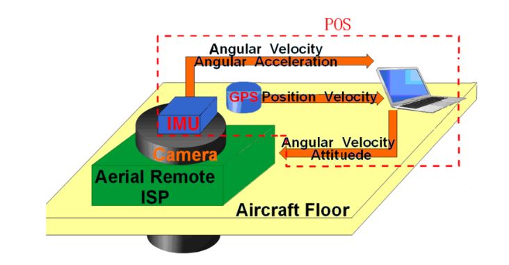
Figure 1. Schematic diagram of an aerial remote sensing system
Figure 3 shows the block diagram of a three-loop control system for an ISP. Conventional stabilization techniques employ rate gyros, rate integrating gyros, or rate sensors to detect angular rate disturbances of the LOS. The blocks of G-pos, G-spe and G-cur separately represent the controllers in the position loop, speed loop and current loop; the PWM block represents the power amplification used for amplifying the current to drive the torque motor; L represents the inductance of a torque motor and R represents the resistance.
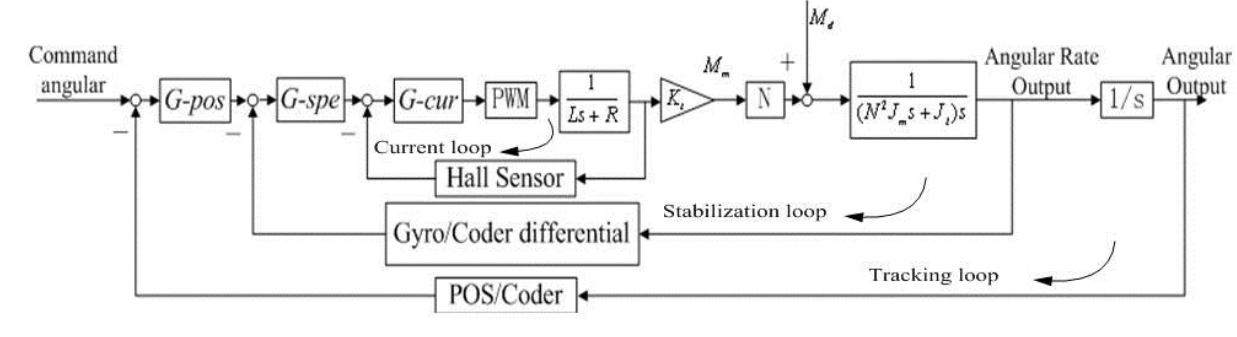
Figure 3. A block diagram of a traditional three-loop control system for an ISP
THREE DIMENSIONAL CAD MODELING
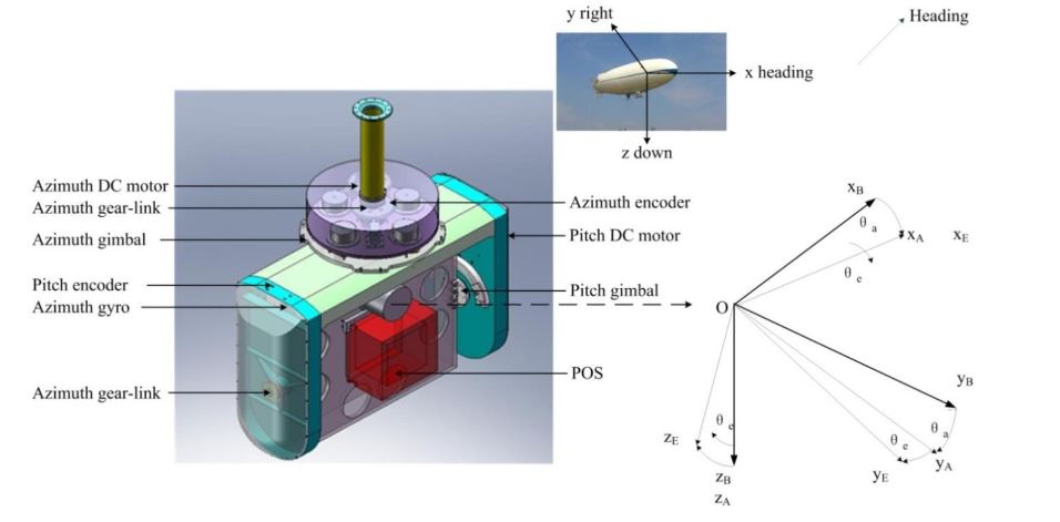
Figure 4. Three-dimensional CAD structural model of a two-axis ISP built using SOLIDWORKS®
Figure 4 shows a three-dimensional CAD structural model of a two-axis ISP built using the three-dimensional parametric CAD software SOLIDWORKS®. The model represents a compromise between a series of conflicting requirements, such as small size and heavy load capacity, light weight and high stiffness, etc., which has to undergo appropriate modifications to realize optimization by adjusting parameters.
It can been seen that the two-axis ISP is mainly made up of five sub-systems, i.e., shaft supporting load system, gimbal structure system, control system, inertial measurement system and drive-transmission system, by which the main function of disturbance rejection can be realized in real-time.
SYSTEM DYNAMICS MODELING AND ANALYSIS
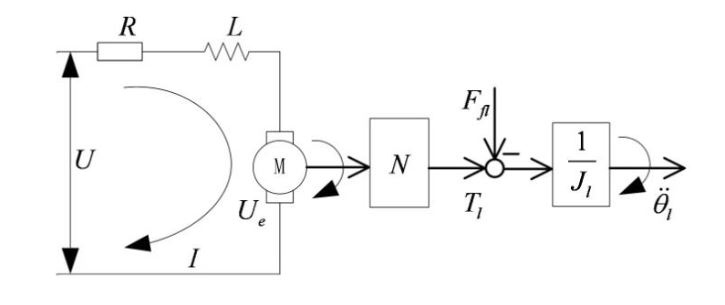
Figure 7. Block diagram for a simplified gear drive system with fixed transmission ratio
Since the maximum required velocity of an ISP is usually low, gearing are used to reduce the size and weight of the actuator, particularly when the torque requirements are demanding. Therefore, to meet the requirements of highly driving torque, heavy load and small size, etc., both gimbals are designed to be rotated by indirect drive motors linked to each gimbal through gear-trains. The gear drive system model, as shown in Figure 4, can be simplified with a fixed transmission ratio, as shown in Figure 7.
CO-MODELING OF THE MECHATRONIC SYSTEM
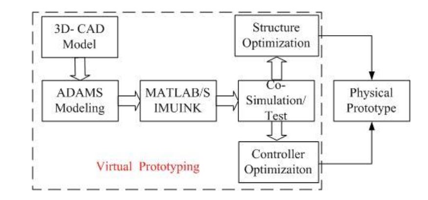
Figure 8. Flow chart of electro-mechanical co-simulation
The co-modeling of the mechatronic system involves two aspects: mechanical system modeling and control system modeling. When the mechanical models are established, the dynamic performance of the system can be improved by mode simulation analysis and structural optimization, which is the basis of the control system design. When the control system parameters are optimized, the high-fidelity VP based on ADAMS™ and SIMULINK® cooperation can be used for the performance testing, visualization simulation of the electromechanical system, control system parameter optimization, and reliability prediction, etc.
CO-SIMULATION AND TESTING
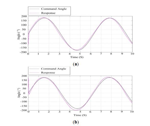
Figure 17. Response curves of ISP at the wind speed of 10 m/s: (a) the azimuth gimbal; (b) the pitch gimbal
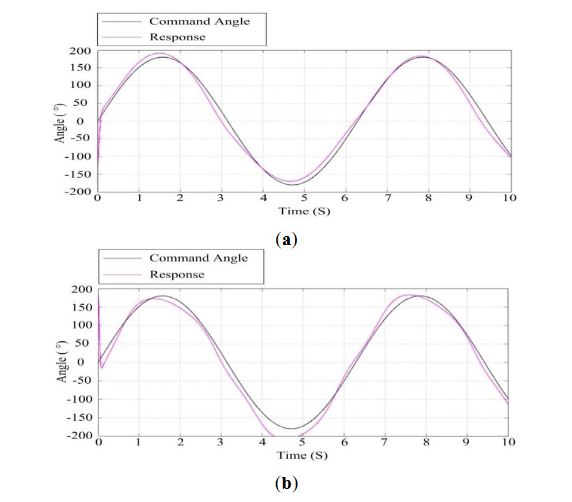
Figure 18. Response curves of the ISP at the speed of 14 m/s: (a) the azimuth gimbal; (b) the pitch gimbal
Figures 17 and 18 show the results of simulation test s under different wind speeds by applying a wind force disturbance to the ISP. Comparing Figure 17 with Figure 18, we can see that when the wind speed is 10 m/s, the azimuth gimbal and the pitch gimbal of the ISP have better tracking performance than that when the wind speed is 14 m/s. This means when the wind speed is larger, the tracking performance of the ISP will decrease, particularly for the pitch gimbal. Therefore, we can determine the wind speed reliability range to guarantee the stabilization performance of ISP.
EXPERIMENTAL VERIFICATION
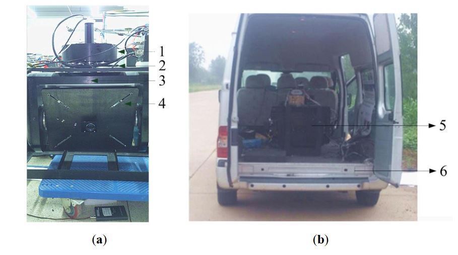
Figure 19. Picture of the ISP during experiments under movable base conditions
Figure 19 shows a picture of our real experimental two-axis ISP system and the movable vehicle. The ISP originally works with the control parameters optimized by co-simulation. Then, the parameters are further optimized and improved based on actual electromechanical tests. The eventual control parameters are based on those of co-simulation and only differ very little from the simulation results. This illustrates that the co-simulation is an important way to design control systems with high performance.
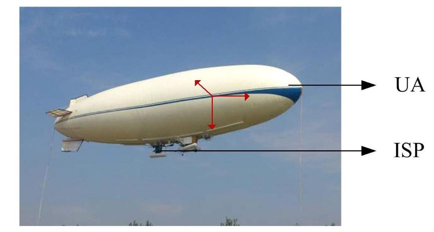
Figure 21. The experiments with a two-axis ISP system on a UA in the air
Figure 21 shows a picture of an experiment with a two-axis ISP system on an UA in air. The control parameters are those determined in the movable vehicle experiments. Figure 22 shows the ISP tracking results of the experiments on a real UA in the air. It can be seen that under the real conditions of the UA in the air, the ISP still has high tracking accuracy with the instruction command, which is similar to the results in the movable vehicle experiments.
CONCLUSIONS
In this paper, to realize high control performance of a two-axis ISP applied in UAs, a method based on co-simulation of the mechatronic system is proposed to optimize the control parameters. Depending on the built three-dimensional CAD structural model, the dynamics model is established under an ADAMS™ environment, by which the main dynamic parameters are obtained through simulation analysis.
Then, the dynamic parameters are input into the SIMULINK® controller to simulate and test the performance of the control system to optimize the control parameters. Experiments were carried out to verify the method. The results show that the proposed method is effective in that it can obviously improve the accuracy and reliability of the ISP.
Source: Beihang University
Authors: Xiangyang Zhou | Beilei Zhao | Guohao Gong
>> More Internet of Things (IoT) Diy Projects for Engineering Students
>> 200+ Matlab Projects based on Control System for Engineering Students