ABSTRACT
This paper describes the design of a high-efficiency vehicular roof-mounted antenna for wireless access for vehicular environment (WAVE) communication systems used for ubiquitous intelligent systems. The main objective of the ubiquitous intelligent system’s automotive IT technology is to enhance the connectivity among vehicles to ensure seamless communication and to reduce the initial access time using high-performance antenna systems.
The efficiency of WAVE communication systems used for ubiquitous intelligent systems depends on the antenna efficiency. The proposed vehicular antenna for WAVE communication systems shows an improvement of approximately 4.77 dB in the return loss, as compared with a conventional antenna system.
ANTENNA DESIGN
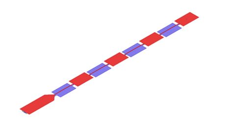
Figure 1. Proposed antenna structure
It is critical for vehicular antennas for WAVE communication systems to exhibit a high gain over the field of view (FOV) of the beam pattern, with a low return loss. To satisfy these two main objectives, we designed an array antenna structure, as shown in Figure 1. This structure consists of four small rectangular segments that are used to generate the required resonant frequency.
RESULTS AND ANALYSIS
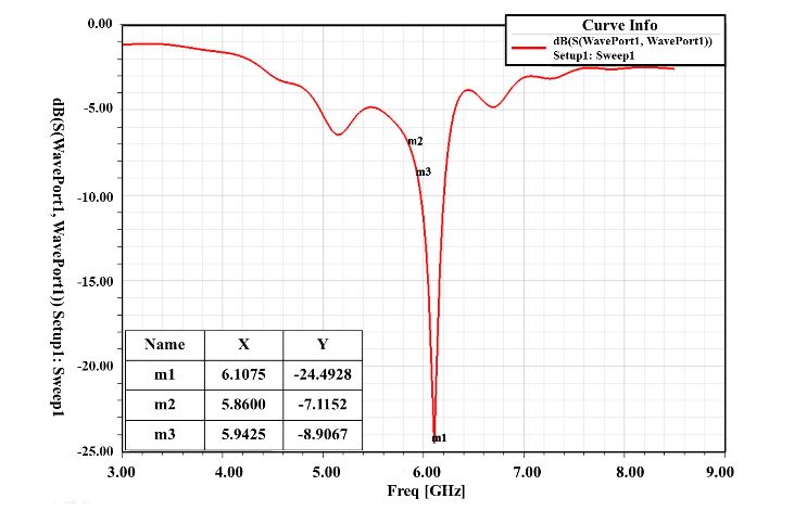
Figure 4. Simulation result of return loss
The FOV for WAVE communication systems is elevated at an angle of 15° above the edge to center. However, only an omnidirectional FOV is required by consumers. Figure 4 shows the simulated return loss of the proposed WAVE antenna. The simulation results show that the proposed array antenna model improves the return loss from −24.47 dB to −19.70 dB.
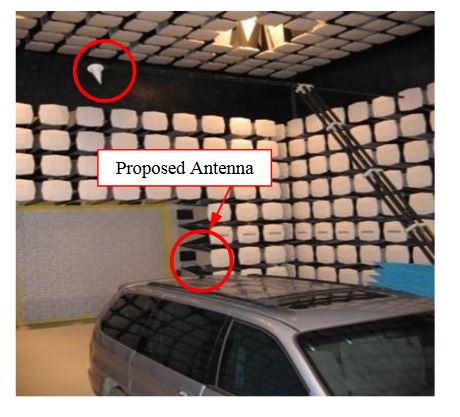
Figure 11. Anechoic chamber in KATECH for antenna measurements
The analytical solution of the array in space shows a gain of 7 dBi for the radiation component. This reference value is used to analyze the following high-frequency structure simulation systems. The results of the measurement analysis show that the surface current is distributed on the metallic parts of the vehicle body. The intensity of this current is expressed in terms of the azimuth and elevation angles. Figure 11 shows the excited antenna measurement equipment in the backlight of the vehicle.
CONCLUSION
This paper presents the design of a high-performance vehicular array antenna for WAVE communication systems. The proposed antenna exhibits an array structure to achieve an improvement in its performance in terms of its return loss, VSWR, and beam pattern, as compared with that of the conventional antenna model.
Further, the simulation results show that the proposed array antenna improves both the return loss by up to 4.77 dB and the gain over the FOV by up to 3 dB, as compared with the conventional antenna model. The results of this study show that the proposed antenna for WAVE communication systems can enhance connectivity among vehicles to ensure seamless communication.
Source: Ulsan University
Authors: Kyubong Yeon | Duho Lee | Byeongwoo Kim
>> 60+ Antenna Communication Projects for Engineering Students
>> 60+ Final Year Projects on Microstrip Antenna Design for Engineering Students