ABSTRACT
In Microwave Monolithic Integrated Circuits, crossovers maintain signal purity when transmission lines overlap with each other. A simple crossover for dual band applications, particularly suitable for the development of smart antennas, is presented in this paper. Derived from conventional patch antenna, the proposed crossovers are easy to design and fabricate, thus reducing the overall complexity.
Design is verified for a dual band crossover at 2.4/5.23 GHz on FR4 (Fiberglass Reinforced) epoxy and tested using Keysight E5080 A Vector Network Analyzer. The results obtained by simulation and measurement are in agreement. The proposed crossovers find application in a Butler matrix for phased array and smart antenna systems.
CROSSOVER
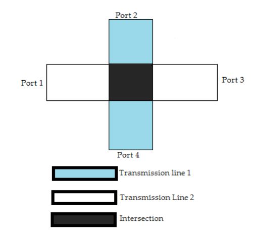
Figure 1. Crossover
Intersection of transmission lines in a circuit leads to reduced signal‐to‐noise ratio (SNR). A ‘crossover’ at the intersection addresses this effectively. As presented in Figure 1, the crossover has decoupled adjacent ports with power maintained between opposite ports.
MICROSTRIP PATCH RECONFIGURED AS PLANAR CROSSOVER
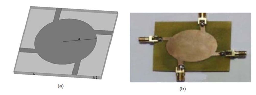
Figure 2. Circular Patch Crossover(CPC). (a) Schematic of CPC; (b) Photo of the fabricated prototype
For initial analysis, a circular patch is modified as crossover as shown in Figure 2. The patch is energized at four locations using 50 Ω microstrip lines, making adjacent ports to have orthogonal polarization.
MICROSTRIP PATCH RECONFIGURED AS DUAL BAND PLANAR CROSSOVER
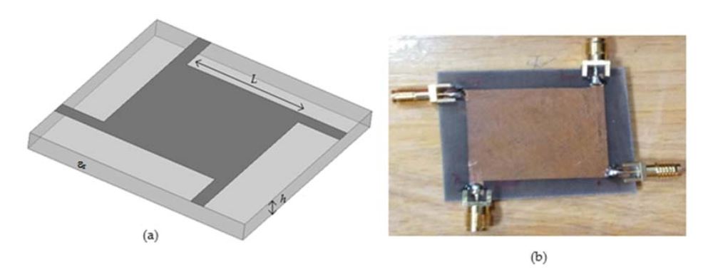
Figure 4. Square Patch Crossover (SPC). (a) Schematic of SPC; (b) Photo of the fabricated prototype
A square patch crossover (SPC) is realized by replacing the transmission line intersection with half‐wavelength square patch excited with two sets of perpendicular feed lines as demonstrated in Figure 4.
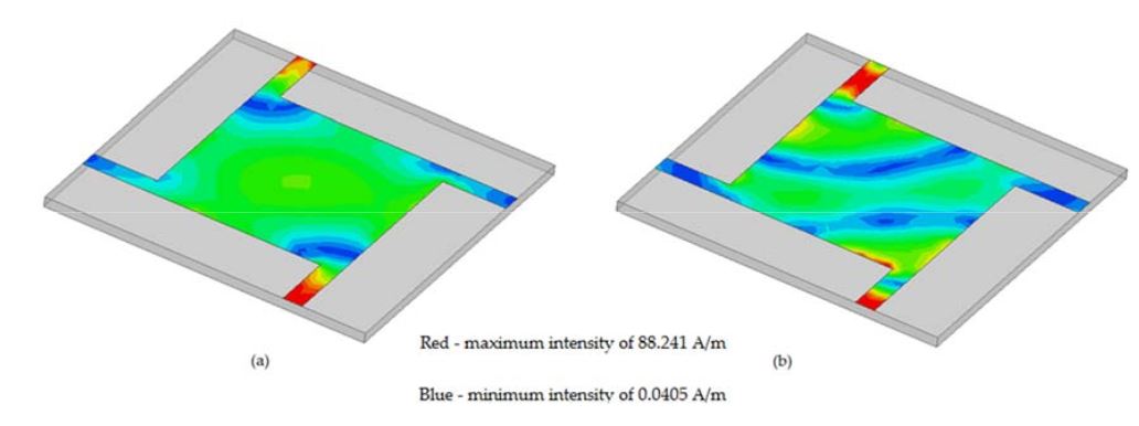
Figure 6. Current distribution of Square Patch Crossover: (a) at 2.43 GHz; (b) at 5.2 GHz.
The current distribution obtained confirms the use of the square patch as effective crossover and is presented in Figure 6. It can be seen that diagonally opposite ports show the same polarization, thus allowing signal flow between them for both the frequencies.
DISCUSSION
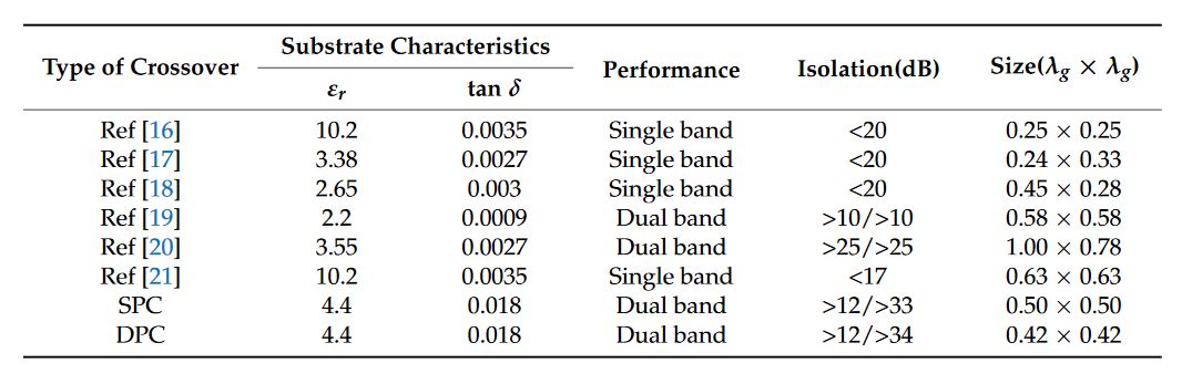
Table 2. Comparison of Crossovers
The performance of the proposed crossover compared to the others to which this paper has referred is presented in Table 2. The reduction in isolation for the first band is due to the high loss tangent of FR4 which could be appreciably improved on using low loss substrates.
CONCLUSIONS
In this paper a new microstrip patch antenna assisted planar dual frequency crossover for maintaining signal purity at transmission line intersections is presented. From Table 2, it can be inferred that the proposed crossover is compact compared to the other microstrip counter parts, provides dual frequency operation and is potentially suitable in designing phased array and smart antenna systems.
Source: Amrita University
Authors: Sreedevi K. Menon
>> Antenna Design Based Projects List for Engineering Students
>> Project Report on Microstrip Patch Antenna Design for Final Year Students