ABSTRACT
Due to the ever-increasing data demand of end users, the number of information and communication technology (ICT)-related devices and equipment continues to increase. This induces large amounts of heat emissions, which can cause serious environmental pollution. In recent times, signal transmission systems such as cellular base stations (BSs) have been constructed everywhere and these emit a large carbon footprint.
Large-scale antenna systems (LSASs) that use a large amount of transmission antennas to serve a limited number of users can increase energy efficiency (EE) of BSs based on the beamforming effect, and thus can be a promising candidate to reduce the carbon footprint of the ICT field. In this paper, we discuss the necessary schemes to realize LSASs and show the expected EE gain of the LSAS with enough practicality.
There are many obstacles to realize the high EE LSAS, and even though several studies have shown separate schemes to increase the EE and/or throughput (TP) of LSASs, few have shown combinations of schemes, and presented how much EE gain can be achieved by the schemes in the overall system. Based on the analysis in this paper, we believe more detailed work for the realization of high energy efficient BSs with LSASs is possible because this paper shows the necessary schemes and the maximum achievable energy efficiency gain as a reference.
Extensive analysis and simulation results show that with proper implementation of the power amplifier/RF module and a robust channel estimation scheme, LSASs with 600 transmitter (TX) antennas can achieve 99.4 times more EE gain compared to the current systems, thereby resulting in significant reduction of carbon footprints.
SYSTEM MODEL
Since we consider that in system Nt is much larger than K, we need to map K message signals to each antenna; coincidently, the K message signals should less interfere each other at RXs. For this, the BS should transmit signals with some kind of precoding. Since Nt is very large, linear precoding is tractable for real systems. It is well-known that zero-forcing (ZF) and regularized zero-forcing (RZF) are effective linear precoding techniques.
PERFORMANCE METRIC FOR MEASURING EE GAIN
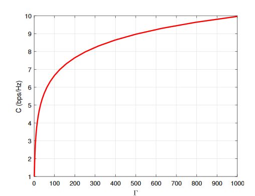
Figure 1. Shannon’s channel capacity versus Γ
As observed, there are roughly two regions in the figure of channel capacity versus Γ. In the region where Γ is not sufficiently high, the channel capacity increases significantly as Γ increases. We usually call this region as power limited region. The channel capacity logarithmically increases as Γ increases. Due to this reason, once Γ is high enough, even if Γ continue to increase, it does little help to increase C. We call this region as bandwidth limited region.
EE IMPROVEMENT ISSUES FOR EACH COMPONENT

Figure 3. Examples of antenna form factor with 400 (20 × 20) antennas, antenna spacing 0.5 λ∼2 λ, and carrier frequencies of 2 GHz and 6 GHz
Since an LSAS is a system that integrates a large number of TX antennas in a limited space, the size and form factor of the installation site could be a problem. The antenna spacing should be at least 0.5 λ, and in addition, since LSASs transmit different signals from each antenna, it is necessary to further increase the antenna spacing to reduce the correlation among the antennas. We present an example of antenna form factors in Figure 3.
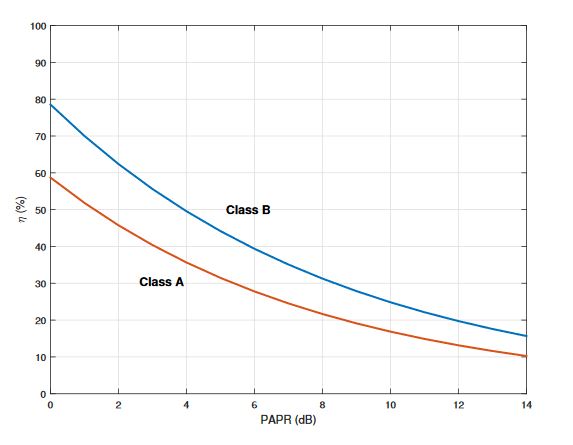
Figure 5. PA efficiency, η (%) versus peak-to-average power ratio (PAPR) (dB)
Regarding the peak-to-average power ratio reduction scheme, the clipping scheme can be acceptable, since it is the most simple and effective peak-to-average power ratio reduction scheme. Due to this reason, we set the efficiency of the PA as 25% for the LSAS. Figure 5 shows the PA efficiency versus peak-to-average power ratio (dB). The 25% PA efficiency is equivalent to 10 dB peak-to-average power ratio or Input Back-off.
SUMMARY AND DISCUSSION
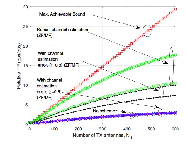
Figure 12. Relative TP gain as Nt increases
We summarize the expected throughput (TP) and EE gain of LSAS for each component with relevant schemes in Figures 12 and 13. As observed, all of the mentioned technologies are important to increase EE. ‘No scheme’ indicates using existing BS technologies for the LSAS. As we can see, even though we can achieve a relative increase of TP as Nt increases using existing technologies, there is no EE gain due to the high power consumption from RF components connected to each antenna.
CONCLUSIONS
In this paper, we have presented the expected achievable gain of energy efficient cellular BSs with LSASs for Green ICT. Environmental pollution from ICT is on the rise, and it is very important to increase the EE of ICT to reduce the carbon footprint. In this regard, we have investigated the LSAS which can be used as a core signal transmission system, cellular BS that significantly increase the EE of ICT field. There are a lot of obstacles and necessary schemes for the realization of LSAS, and we have viewed related issues one by one and estimated how much EE gain can be achieved from each scheme.
The cellular BS is one of the most power hungry ICT devices, thus increasing EE of the cellular BS is particularly important. We discussed the detailed research obstacles for the EE improvement of BS and showed that the obstacles should be solved together to improve the EE. We also showed that we can achieve 99.4 times EE improvement, and this figure can be a good reference for the future research.
The main technical challenges of LSAS we pointed-out in the previous sections are (I) design of efficient antenna elements and antenna form factor; (II) design of low power PA/RF components; (III) channel estimation and reference signal overhead reduction. The compact antenna, and low power PA/RF components are related to implementation issues. Typically antenna form factor problem is diminished if we use high carrier frequency range, like mmWave range. However, we should overcome the poor channel condition. Low power PA/RF component is also an active research field.
Due to the excessive channel gain, low power PA and relative coarse RF components could be also acceptable for LSAS. Channel estimation for LSAS is particularly difficult to resolve. Research related to using uplink channel sounding in time division duplexing (TDD) based system and using compressed feedback information are actively going-on. This paper can be a good reference for the realization of high EE BS, which gives a great benefit for environmental protection.
Source: Sejong University
Author: Byung Moo Lee
>> 60+ Antenna Communication Projects for Engineering Students