ABSTRACT
The poses of base station antennas play an important role in cellular network optimization. Existing methods of pose estimation are based on physical measurements performed either by tower climbers or using additional sensors attached to antennas. In this paper, we present a novel non-contact method of antenna pose measurement based on multi-view images of the antenna and inertial measurement unit (IMU) data captured by a mobile phone.
Given a known 3D model of the antenna, we first estimate the antenna pose relative to the phone camera from the multi-view images and then employ the corresponding IMU data to transform the pose from the camera coordinate frame into the Earth coordinate frame. To enhance the resulting accuracy, we improve existing camera-IMU calibration models by introducing additional degrees of freedom between the IMU sensors and defining a new error metric based on both the downtilt and azimuth angles, instead of a unified rotational error metric, to refine the calibration.
In comparison with existing camera-IMU calibration methods, our method achieves an improvement in azimuth accuracy of approximately 1.0 degree on average while maintaining the same level of downtilt accuracy. For the pose estimation in the camera coordinate frame, we propose an automatic method of initializing the optimization solver and generating bounding constraints on the resulting pose to achieve better accuracy.
With this initialization, state-of-the-art visual pose estimation methods yield satisfactory results in more than 75% of cases when plugged into our pipeline, and our solution, which takes advantage of the constraints, achieves even lower estimation errors on the downtilt and azimuth angles, both on average (0.13 and 0.3 degrees lower, respectively) and in the worst case (0.15 and 7.3 degrees lower, respectively), according to an evaluation conducted on a dataset consisting of 65 groups of data.
We show that both of our enhancements contribute to the performance improvement offered by the proposed estimation pipeline, which achieves downtilt and azimuth accuracies of respectively 0.47 and 5.6 degrees on average and 1.38 and 12.0 degrees in the worst case, thereby satisfying the accuracy requirements for network optimization in the telecommunication industry.
RELATED WORK
There is a vast amount of literature related to pose estimation problems, and the most important and most closely related studies are those concerning visual pose estimation and visual-inertial fusion. We will focus on techniques that specifically address visual pose estimation of rigid objects with known geometries and sparse textures, as well as techniques for camera-IMU calibration, which is a key component of visual-inertial fusion.
PROBLEM FORMULATION AND METHOD OVERVIEW
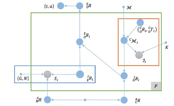
Figure 2. The antenna pose estimation problem represented as a graph model. Filled blue circles represent unknown quantities
Referring to the original graph model presented in Figure 2, we find that the first item in Equation (2a), which corresponds to the red-outlined region in the upper right of the figure, describes P model-based visual pose estimation problems, and similarly, the second item, corresponding to the blue-outlined region in the lower left of Figure 2.
RELATIVE POSES BETWEEN THE CAMERA AND IMU SENSORS
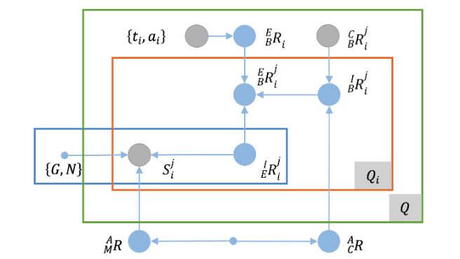
Figure 4. The camera-IMU calibration problem represented as a graph model
Then, we can model the calibration using a graph model similar to that presented for the antenna pose estimation problem, as shown in Figure 4. Unlike in the case of the antenna pose estimation problem, because of the maturity of camera calibration techniques, the relative pose between the camera and the checkerboard is considered to be known, and the downtilt and azimuth angles of the checkerboard are regarded as the ground truth.
ANTENNA POSES ESTIMATED FROM CAPTURED IMAGES
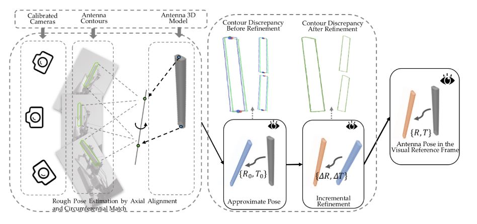
Figure 7. As shown in the leftmost box, the position of the 3D principal axis is recovered from multi-view contours
As shown in the leftmost box, the position of the 3D principal axis is recovered from multi-view contours (green), and the 3D antenna model (gray) is aligned with the recovered axis and rotated to find a coarse estimate of the antenna pose. As shown in the left column of the middle box, there are discrepancies between the antenna contours and the projections from the approximate pose (blue), and as shown in the right column, the approximate pose can be globally refined to reduce the contour discrepancy with respect to the resulting refined pose (pink). In the rightmost box, the final overall estimation result is shown as the transformation from the model frame (gray) to the reference frame (pink).
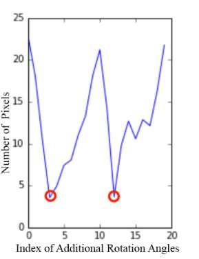
Figure 9. Removal of the rotational uncertainty about the (recovered) 3D principal axis
Removal of the rotational uncertainty about the (recovered) 3D principal axis. The antenna model is rotated around the recovered principal axis with a fixed step size (X axis), and the average difference between the antenna widths at the center in the projections and the real images (Y axis) is treated as the cost that represents the degree of closeness between the current pose and the ground truth. Two minima are clearly observed.
EXPERIMENTAL RESULTS
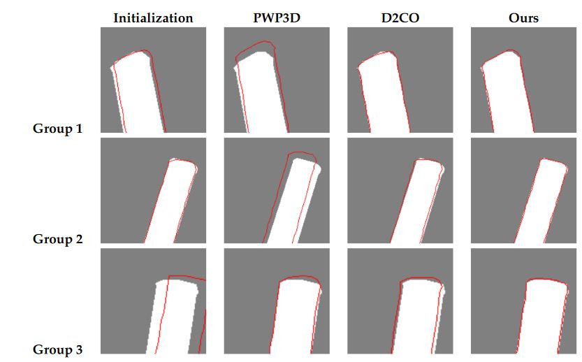
Figure 12. Examples from three groups of data (a single viewpoint for each) for which Pixel-Wise Posteriors for 3D tracking and segmentation (PWP3D)
To ensure a fair comparison, we slightly modified the two existing methods. For PWP3D, we used the multi-view version and replaced the foreground/background probabilistic model with a deterministic one based on antenna silhouettes to eliminate errors in its segmentation step; for D2CO, we trivially extended it to obtain a multi-view version by accumulating the costs from each view, which is the strategy adopted in PWP3D. To initiate each method, we used our approximate poses, whose projections in each view show extensive overlap with the ground truth, as shown in the first column of Figure 12.
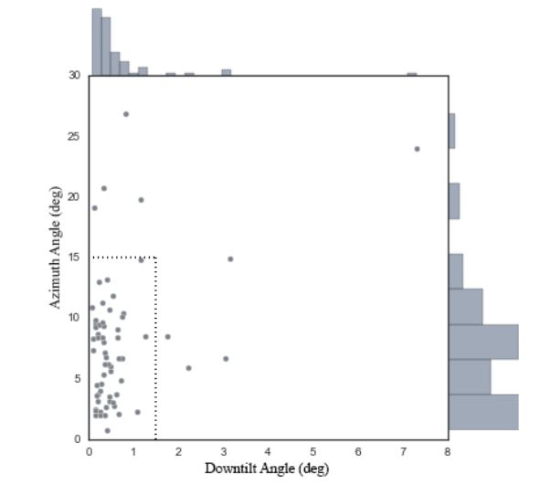
Figure 14. The estimation errors for each group of data from AntennaS when the camera was extrinsically calibrated using an SfM technique implemented in OpenMVG
Figure 14 and Table 5 show the resulting estimation errors. Whereas nine out of 65 (or 13.8%) of the data cases failed to yield an estimate with a downtilt error of no more than 1.5 degrees and an azimuth error of no more than 15 degrees when the SfM technique was used, as seen from Figure 14, the majority of the results (at least 75%) show a precision comparable to that of the results obtained using a calibration pattern, as indicated by the first three quartiles reported in Table 5.
DISCUSSION AND CONCLUSIONS
The focus of our study is the development of a novel non-contact solution for estimating antenna tilt and azimuth angles using a mobile phone as the measuring device. The two key points of our pipeline are the newly proposed camera-IMU calibration method for mobile phones and the coarse-to-fine visual pose estimation method. The major difference between our camera-IMU calibration method and the state-of-the-art is the inclusion of additional DoFs between the accelerometer frame and the magnetometer frame, which allows for decoupling of the accelerometer-related error and the magnetometer-related error and therefore leads to good performance on both tilt and azimuth estimation tasks simultaneously.
The crucial distinction between our visual pose estimation method and existing ones is the coarse-to-fine strategy we adopt. With this strategy, we avoid any manual pose initialization and more importantly are able to refine the approximate pose as a constrained optimization problem for higher accuracy compared with the state-of-the-art. Besides, our method is based on multi-view contours instead of stable visual feature, which makes it very suitable for pose estimation of the textureless and simple-shaped antennas.
Source: Zhejiang University
Authors: Zhen Wang | Bingwen Jin | Weidong Geng
>> 60+ Antenna Communication Projects for Engineering Students