ABSTRACT
In recent years, the interest in quadcopters as a robotics platform for autonomous photography has increased. This is due to their small size and mobility, which allow them to reach places that are difficult or even impossible for humans. This thesis focuses on the design of an autonomous quadcopter videographer, i.e. a quadcopter capable of capturing good footage of a specific subject. In order to obtain this footage, the system needs to choose appropriate vantage points and control the quadcopter. Skilled human videographers can easily spot good filming locations where the subject and its actions can be seen clearly in the resulting video footage, but translating this knowledge to a robot can be complex.
We present an autonomous system implemented on a commercially available quadcopter that achieves this using only the monocular information and an accelerometer. Our system has two vantage point selection strategies: 1) a reactive approach, which moves the robot to a fixed location with respect to the human and 2) the combination of the reactive approach and a POMDP planner that considers the target’s movement intentions. We compare the behavior of these two approaches under different target movement scenarios. The results show that the POMDP planner obtains more stable footage with less quadcopter motion.
PLATFORM
Quadcopter Flight
The position is maintained by rotating one set of opposing propellers clockwise, while rotating the other pair counter-clockwise (Figure 2.1(a)). This allows for the cancellation of the total torque in the vehicle and with enough thrust, the nullification of gravity.By increasing the velocity of the four propellers by the same amount and thus generating more overall thrust without creating torque, the copter is able to maneuver in a vertical line (along the z-axis) (Figure 2.1(b)). Horizontal movement is achieved by increasing the velocity of one propeller and by decreasing the velocity of the opposite propeller (Figure 2.1(c)). Finally, to change the direction of the robot (its yaw angle), two opposite propellers are accelerated (Figure 2.1(d)). This creates a torque in the robot and thus an angular acceleration that changes the yaw angle.
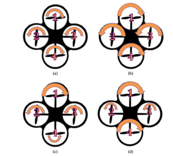
Figure 2.1: Basic Quadcopter Flight: The size of the arrows represents the amount of rotational speed (bigger arrows represent higher speeds). (a) Maintain position, (b) Move up, (c) Move forward, (d) Rotate clockwise
Parrot AR.Drone Hardware and Software
AR.Drone 2.0, the next generation of the quadcopter, was released in 2012. This version includes some improvements in the hardware and is the one used in the experiments. The following section presents some specific details on the hardware of the AR.Drone 2.0 and its API.The Parrot AR.Drone comes equipped with 2 hulls, which are possible body protections as can be seen in Figure 2.2.
The indoor hull protects the quadcopter from collisions with other objects, which can happen easily when flying in cluttered environments. The outdoor hull does not provide protection for the propellers, but its smaller weight allows for a more stable flight and better maneuverability. All communications between the drone and the outside world are performed via WiFi. For this, the AR.Drone creates a wireless LAN network as soon as the battery is connected.
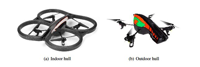
Figure 2.2: AR.Drone 2.0 and its different hull options
FACE LOCALIZATION
Face Detection and Alignment
Face alignment is the process of identifying key landmarks in a detected face. As example of its results can be seen in Figure 3.2, where the edges in the second picture are defined by the pixel locations of the landmarks. For our project, we used the method by Kazemi and Sullivan, which uses an ensemble of regression trees to estimate the shape from an initial configuration. Specifically, they used a cascade of regressors, where each one predicts an update vector from the image and the current shape estimate.
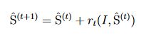
Figure 3.2: Face alignment: (a) Original figure where a face has been detected (b) Landmarks identified by the face alignment process
Face Pose Estimation
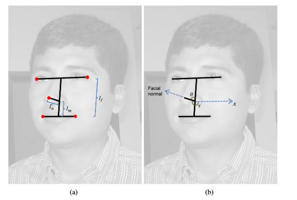
Figure 3.4: Face pose estimation
(a) The landmarks used in the 3D method are shown as red dots, as well as the distances used in the calculation of the pose (b) Angles used in the method. The facial normal is determined by the nose tip, and our method calculates the slant angle σ to obtain the normal.
CONTROL
The main goal of this area is to control a system in such a way that its output signal, the measured output, matches a reference signal.
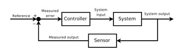
Figure 4.1: Feedback loop in control theory, via Wikimedia Commons / CC BY-SA 3
Reactive Behavior for Quadcopter Autonomous Navigation
Finally, the yaw component is calculated differently. Although our intention is that the robot faces the human subject once it is in the goal location, considering only the final yaw may cause the robot to lose the sight of the person. For this reason, we instead try to maintain the robot always pointing towards the human subject. For example, consider the case in Figure 4.3, the command for the robot will be to rotate towards its left so that it keeps seeing the human. If this logic is maintained through the quadcopter flight motion, it will be facing the subject at its destination.
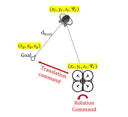
Figure 4.3: Reactive Behavior: The goal location is calculated as d front meters in front of the person. The height of the goal is d height meters above the location of the eyes.
PLANNING USING POMDPS
Intention Aware Quadcopter Videographer Problem
The yaw is defined as the angle of the subject’s face with respect to the quadcopter’s front-facing camera. An angle of zero would mean that the human is facing parallel to the camera (see Figure 5.2(b)).

Figure 5.2: POMDP quadcopter world: the location is calculated by discretizing the distance from the goal, and the yaw is calculated by discretizing the yaw between -90°and 90°.
In each time step, the agent receives a noisy reading of the location and yaw of the subject. This observation is used to update the belief about the current state including the intentions that are not directly observed. For this, we model the transition probabilities as shown in Figure 5.3.
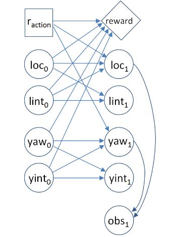
Figure 5.3: POMDP for the Intention Aware Quadcopter Videographer Problem
IMPLEMENTATION
System Architecture
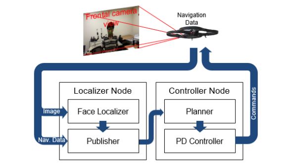
Figure 6.1: System Architecture
Every time a new image is received (from the quadcopter’s frontal camera), the face detection, alignment, and pose estimation processes are executed as detailed in Chapter 3. These tasks are performed in the face localizer sub module (Figure 6.1). A practical consideration is that the frontal camera in the AR.Drone exhibits a high degree of radial distortion, which if not corrected significantly degrades the localization estimates. The straightforward solution of warping each image to undo the distortion is computationally unattractive.
EXPERIMENTAL RESULTS
Our physical testing environment was a room 7.5 by 4.0 meters long, with a height of 2.7 meters. We executed several runs, which consisted of five minutes of autonomous control of the quadcopter with a single subject in the room (who moves during the experiment). For each run, we first started the quadcopter (taking-off) manually, while the human was located in front of the drone at a distance between 1.5 and 2.0 meters. This served as an initialization so that the robot is positioned when the autonomous controller starts.
CONCLUSION AND FUTURE WORK
This thesis describes an autonomous quadcopter videographer that detects and tracks a human subject’s face. Our solution primarily employs monocular information, which is obtained from the frontal camera and processed to estimate the subject’s pose. We evaluate the performance of two vantage point selection strategies: 1) a PD controller that tracks the subject’s head pose and 2) combining the reactive system with a POMDP planner that considers the subject’s movement intentions. The POMDP is able to filter short motions and reacts only when the human moves farther or rotates more. As a result, this controller executes less motion, thus obtaining more stable video sequences than the PD controller alone.
Source: University of Central Florida
Author: Quiquia Rey Coaguila