ABSTRACT
This paper proposes an efficient management system utilizing a Radio Frequency Identification (RFID) antenna control unit which is moving along with the path of boxes of materials on the conveyor belt by manipulating a motor. The proposed antenna control unit, which is driven by a motor and is located on top of the gate, has an array structure of two antennas with parallel connection.
The array structure helps improve the directivity of antenna beam pattern and the readable RFID distance due to its configuration. In the experiments, as the control unit follows moving materials, the reading time has been improved by almost three-fold compared to an RFID system employing conventional fixed antennas. The proposed system also has a recognition rate of over 99% without additional antennas for detecting the sides of a box of materials.
The recognition rate meets the conditions recommended by the Electronic Product Code global network (EPC) global for commercializing the system, with three antennas at a 20 dBm power of reader and a conveyor belt speed of 3.17 m/s. This will enable a host of new RFID conveyor belt gate systems with increased performance.
CONVENTIONAL RFID PORTAL SYSTEMS
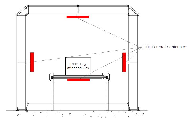
Figure 3. The RFID conveyor belt gate structure proposed by EPC global
The experimental setup proposed by EPC global (see Figure 3) has four antennas located on four faces of the gate. This method can be evaluated with the assumption that RFID tags are attached on all faces of a box passing through conveyor system. The experimental conditions of the proposed conveyor belt gate system with antenna control unit based on the experimental standards of EPC global will be discussed in Section 3.
DESIGN OF THE ANTENNA CONTROL UNIT
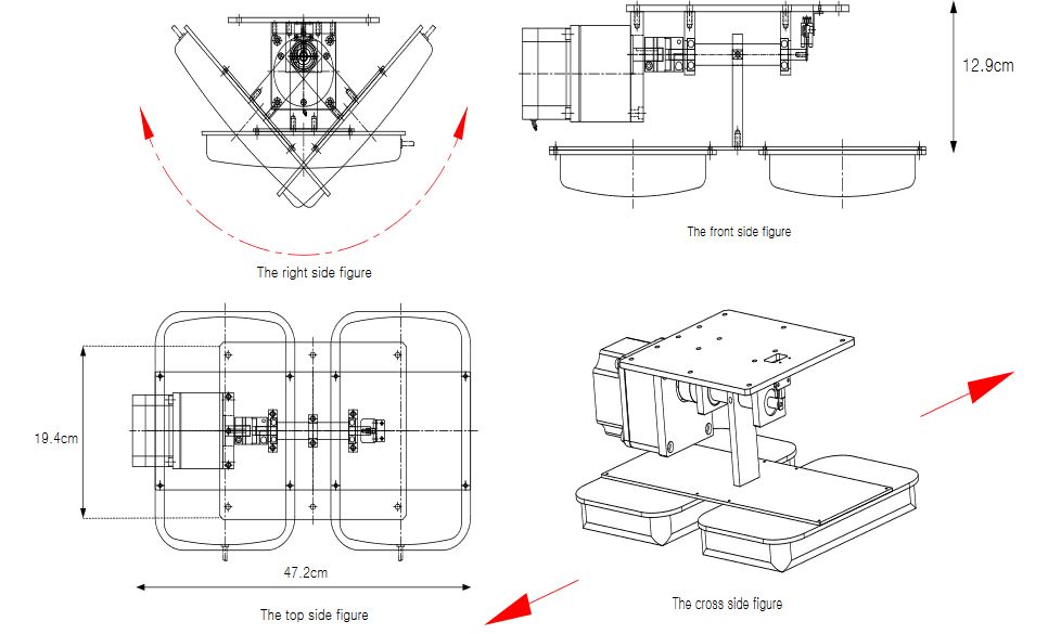
Figure 5. A drawing of the antenna control unit
Since the antenna control unit is designed to extend the readable distance by arraying two antennas, it rotates with an operating range of 45° for both the front and back sides of the gate for effective tag identification. This can help to prevent unnecessary reading action of the antenna control unit for effective recognition of materials with in gate boundaries. Figure 5 shows drawings of the designed antenna control unit.
IMPLEMENTATION AND EXPERIMENTAL RESULTS
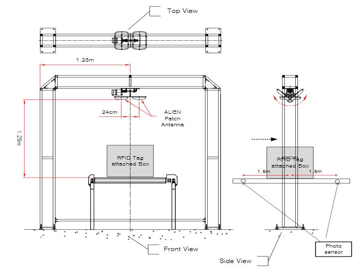
Figure 6. An experimental structure
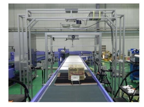
Figure 7. A picture of the experimental site with two antennas
This section shows the result of experiments performed at the RFID/USN center recommended by EPCglobal in Song-do, Incheon, Korea. Figure 6 depicts the way in which the parts of an experiment are arranged, and Figure 7 shows an actual experimental site.
CONCLUSIONS
This paper presents a RFID conveyor belt gate system with a novel concept, utilizing an antenna control unit. In order to improve the recognition rate of the antenna, we have arranged two commercial antennas in the same row instead of designing an array antenna. Controlling the antenna to move along with materials has provided longer reading times to the system.
The experimental results with the proposed novel structure show recognition rate s of 97–99% which are the same as or better than the results of commercial structures employing multiple antennas and fixed structure of the same configuration. The proposed system has the potential to open a new regime for the design and use of RFID conveyor belt systems.
Source: Dongguk University
Authors: Chong Ryol Park | Seung Joon Lee | Ki Hwan Eom
>> 60+ Final Year Projects on Microstrip Antenna Design for Engineering Students