ABSTRACT
The main goal of this research is to design a snake-like robot arm to provide control of a cardiac catheter for use in endovascular aortic repair that is small, cheap, and easy to use. This will help increase the number of aortic aneurysms eligible for endovascular repair and make the procedure simpler and safer for both the patient and the operator.
The arm surrounds the catheter and is comprised of two joints that can independently move in any direction giving the operator the ability to easily navigate complicated paths and to control the arm remotely. The arm is controlled by Flexinol actuator wire which is comprised of a nickel titanium alloy that contracts when heated.
This allows the arm to be controlled electrically by sending current through the actuator wire thereby heating it. The level of current can be controlled using a microcontroller to generate a pulse width modulated signal to vary the average current. The arm can then be controlled remotely by an operator.
ENDOVASCULAR LIMITATIONS AND ALTERNATIVE SOLUTIONS
In this chapter, we will explore the background of endovascular aortic repair procedures and how they are limited by current technology. We will discuss the areas where robotics could solve these limitations and talk about previous technologies that attempt to do so.
PROTOTYPE MODEL
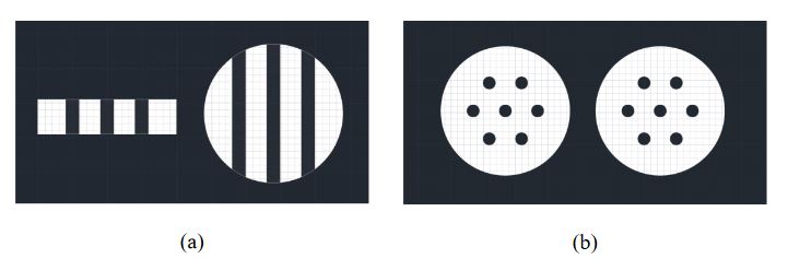
Figure 3-1 (a) A side cutaway view and (b) a top down view of the sphere and disk that make up the joints
This disk is 2.5 mm thick and is used to provide separation between the joints and act as a connection point for the control wires. Shown in figure 3-1 (a) is a side cutaway view of the disk and sphere. In figure 3-1 (b), it shows the same disk and sphere but from a top down view.
ACTUATOR WIRE
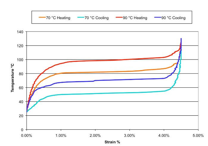
Figure 4-1 Typical Temperature vs. Strain Characteristics for Dynalloy’s standard
The wire is made up of a nickel-titanium alloy and it dynamically changes its internal structure at certain temperatures. Unlike normal thermal expansion, it will contract when heated and exert a large amount of force relative to its size. Figure 4-1 shows the typical temperature vs strain characteristics of the wire at different temperatures.
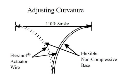
Figure 4-3 Curvature adjustment structure and percent of movement
More important to the usage discussed in this paper is how the wire can affect stroke with different mechanical set ups. In the case of the control arm, the specific setup of interest is one that allows adjusting curvature and how this affects the amount of force provided by the wire. Figure 4-3 shows this structure and the amount of stroke it provides while table 4-1 shows the stroke and available force for all the setups shown so far.
SCALING THE PROTOTYPE
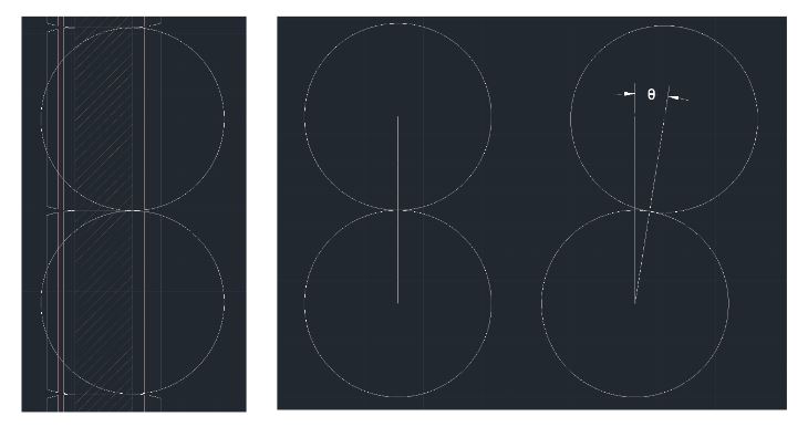
Figure 5-3 Visualizing the joint bend with two circles
The bending angle of the arm is directly related to the amount of contraction in the control wires. To calculate this relationship, it helps to start with one side of the joint and visualize it as circles rolling along one another as shown in figure 5-3. The center of this circle is halfway down the bead on the inner wall of the catheter hole.
CONTROL SYSTEM
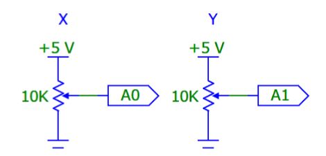
Figure 6-1 X and Y axis potentiometers of the joystick
The joysticks work by combining two 10 KΩ potentiometers, one for each axis as shown in figure 6-1. As the joystick moves along an axis, the potentiometer value changes. A0 and A1 are inputs to an analog to digital converter that sends a digital value between 0 and 1024 to a microcontroller based on the voltage read between 0 and 5 V.
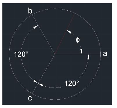
Figure 6-3 Circle showing control wire locations and angle of joystick ɸ
The angle and magnitude are then used to calculate the magnitude of the duty cycle and therefore the magnitude of the current for each control wire. This is illustrated in figure 6-3 where ɸ is the angle of the joystick relative to its left/right or x axis. The control wires are marked as a, b, and c around the circle, each 120 degrees apart.
Source: University of Iowa
Author: Adam Thomas Snyder