ABSTRACT
Robotic systems, when used in real world situations, often have many control modes that need to be switched between in real time. These control modes may be addressing the robots in many different ways and may be executing in different locations. Conventional robot control software platforms do not provide a flexible way of switching between all of the different types of control modes in real time.
In this paper, we present a system architecture that seeks to solve this problem of real time controller switching using industry standard software. The architecture implemented is one that allows for robot control regardless of hardware, and ensures continuity of control when undergoing arbitrary controller switching. Our experiments show that this software can be used to switch between types of controllers, location of controller execution, and single and multi-robot controllers. They also show that switching controllers takes 10ms, which is well within our requirements.
We conclude that our system is useful in its present state for smaller projects at research institutions, or as a stepping off point for future work. To improve this system for general use, improvements beyond solely sending messages through Wi-Fi will be necessary. It is also recommended that this system be transferred from Indigo, the current distribution of ROS used, to Kinetic the newer distribution of ROS, because Indigo is nearing end of life. Despite these recommendations, the success of this project shows how important this type of system will be in continuing robotic development.
BACKGROUND
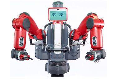
Figure 1.1: Baxter, by Rethink Robotics
In 2017, the most ”general purpose” robot available on the market is the one pictured above in Figure 1, named Baxter. Baxter claims to be the first general purpose robot, and with a price tag of $35k, he’s cheaper than a year’s pay at a minimum wage job. Although he’s in many ways more advanced than many factory robots due to his ability to work safely around humans, is he the general purpose robot we’ve been imagining?
SYSTEM OVERVIEW
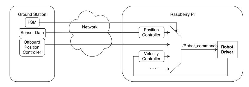
Figure 2.1: A data flow diagram for the software architecture
The system architecture used in this project is shown in Figure 2.1. The Raspberry Pi on the robot is running multiple onboard controllers, as well as taking in commands from off board controllers that are being passed through the network. Any number of controllers can be running and passing through the mux.
HARDWARE IMPLEMENTATION
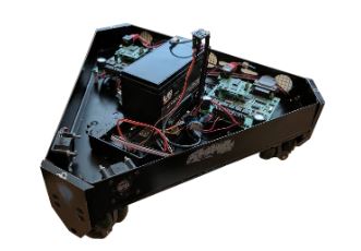
Figure 3.1: The Omnibot robot used in testing
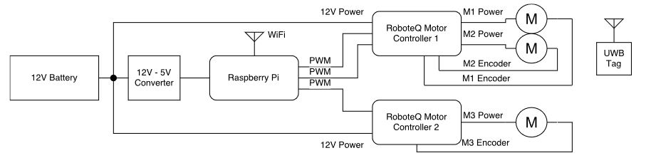
Figure 3.2: Block Diagram of the Omnibot Robot
The primary robot used in testing, named Omnibot, is an omniwheeled holonomic drive robot and has been in use in the lab for well over a decade. Shown in Figure 3.1, the Omnibot is one of two robots with this drivetrain, both of which have been extensively used by Ethan Head in previous years. The other robot, named Reddie, is in use for testing fault tolerance and anomaly management on another RSL project. A block diagram of the Omnibot system is shown in Figure 3.2.
CONTROLLER IMPLEMENTATION
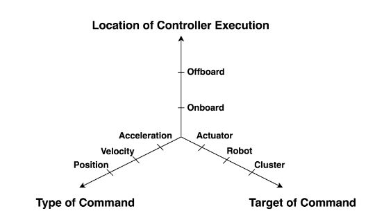
Figure 4.1: Three orthogonal dimensions of classification for controllers
Each of these dimensions enumerates explicitly a type of control message, an endpoint for that control message, or a channel for that data packet. As shown in Figure 4.1, these orthogonal axes completely describe the requirements of their execution. Furthermore, it should be noted that the closer the controller is to the center, the less complex the controller.
SOFTWARE IMPLEMENTATION
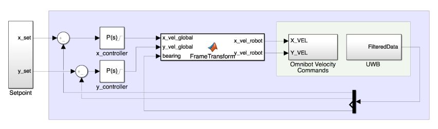
Figure 5.2: A closed loop position controller for the Omnibot and hardware interfacing components
In Figure 5.2 we can see an example of a controller used in our tests. It controls the position of the Omnibot holonomic drive robot in the robot arena at NASA Ames, using the UWB system. UWB feedback is provided to the control loops to determine what direction the robot needs to move in, and the current angle of the robot is provided to a frame transformation function that translates the global velocity command to a robot level velocity command.
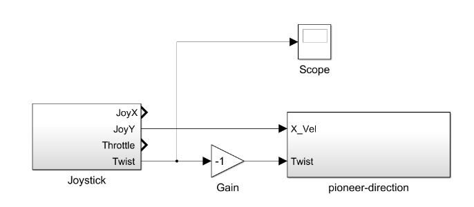
Figure 5.5: A pass through velocity controller for the Pioneer
Figure 5.5 shows the passthrough velocity controller used to control the Pioneer via a gamepad. The two command channels are mapped to the gamepad’s joystick and triggers to control linear and angular velocity respectively. Closed loop control is executed at an actuator level onboard the robot.
SYSTEM TESTING
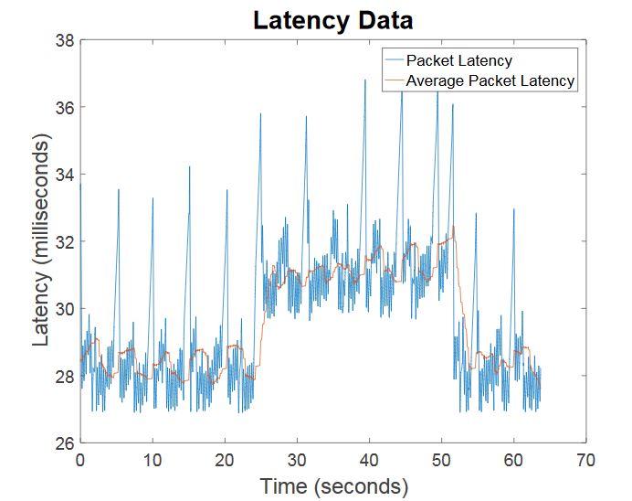
Figure 6.2: The latency graph over time of the test
It is important to address the large spikes in latency. These are caused by the finite state machine updating the set point to a new location for the robot to continue its controller execution. When automating switching based on latency data, this spike can easily be filtered out, as evidenced by the orange line in Figure 6.2 which shows the latency averaged over the last 200 points. This test did not use the 200 point average, and it is just shown as an example averaging function; any user can adjust the window length for their specific purposes.
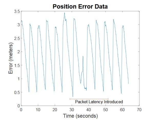
Figure 6.3: The position error graph over time of the test
The average settling time increases with latency, and can also cause erroneous instructions, such as the one seen in Figure 6.3 which even further degrades performance. From the same graph shown in Figure 6.3, we can determine the time it takes to change controllers, which is less than 6ms.
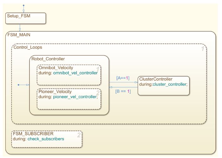
Figure 6.6: The finite state machine used for test 3
Both the Omnibot and Pioneer are used for this test, with one finite state machine, shown in Figure 6.6, controlling both the switching of their controllers. In this test, the robots start being driven by two users, and then are switched in to cluster mode, where the Omnibot snaps to a position relative to Pioneer, and runs a position controller to hold that relative position. The joystick that was controlling Omnibot now changes the set point relative to Pioneer that it tries to hold.
PROFESSIONAL ISSUES
The rapidly rising number of commercial drones available combined with declining prices of these drones are making the ethical questions surrounding them more prominent in the popular media and ethical studies circles. There are many problems surrounding their security, ability to harm humans both in planes and on the ground, and their ability to be misused for surveillance purposes. We will explore these questions and offer our best solutions to them in the context of our project here.
CONCLUSIONS
Summary
A software architecture has been presented that is able to manage execution of controllers across devices that can address systems at actuator, robot, or cluster levels with position or velocity commands. Each permutation of the three dimensions may be switched into another permutation in real time due to driver input or user defined logic. The system allows controllers to abstracted away from the switching logic that routes their signals, and allows controllers to be abstracted away from the hardware that executes their commands.
Future Work
In the future, we believe there is value in implementing this system on aerial vehicles, as the system was developed with that use case in mind. It would also be beneficial to implement this on the DecaBot platform in the RSL. If a team were to pick up the system for next year, we would like to see them implement everything in a newer version of ROS, as the version we used, ROS Indigo, is nearing its end of life.
Source: Santa Clara University
Authors: Ethan Head | Addison Fattor